
1. INTRODUCTION
1.1. About this manual
1.1.1. Copyright Notice
All rights reserved. No part of this document may be reproduced, copied or transmitted in any form by any means electronic, mechanical or otherwise without the permission of Marquise Technologies sàrl. If you are interested in receiving permissions for reproduction or excerpts, please contact us at contact@marquise-tech.com.
1.1.2. Trademarks
Marquise Technologies, the company’s logo and products' logo are pending registration trademarks of Marquise Technologies sàrl. All other trademarks mentioned here within are the property of their respective owners.
1.1.3. Notice of Liability
The information in this document is distributed and provided “as is“ without warranty. While care has been taken during the writing of this document to make the information as accurate as possible, neither the author or Marquise Technologies sàrl shall not be held responsible for losses or damages to any person or entity as a result of using instructions as given in this document.
1.1.4. Conventions
This documentation makes use of several symbols and typographical conventions in order to differentiate various paragraphs from standard descriptive text. Here is the list of symbols and typographical styles used:
|
INFO : Additional information about the current topic. |
|
WARNING : Important information that you should always take into consideration. |
|
TOOL-TIP : Additional information about tool usage |
1.2. About MIST
MIST revolutions the mastering process by offering in one unique solution unrivaled features for the creation of any type of masters or file packages from any type and resolution of source media.
From the RAW data to the final project, MIST provides dailies management, multiple formats transcoding, extensive editing and conforming tools, advanced color grading and color management features, image enhancement and conversion tools.
Whatever the type of master you need to deliver, MIST offers the most intuitive and evident workflow with tools to control and validate the compliance with the standards.
MIST creates and QC deliverables in 4K HDR or ACES content including DCP, IMF, AS-11, X1, AS 10, MXF ProRes, iTunes packages and many more, for distribution in Digital Cinema, broadcast and online.
MIST is available in two versions, MIST Prime and MIST Studio.
| MIST Prime | MIST Studio | |
|---|---|---|
Dailies management |
yes |
yes |
Advanced color grading tools |
yes |
yes |
Editing & Conforming |
yes |
yes |
ACES Workflow |
yes |
yes |
HDR conversions |
yes |
yes |
DCP mastering |
yes |
yes |
DCP HDR mastering |
no |
yes |
IMF mastering |
no |
yes |
Dolby VisionTM Editorial & QC |
no |
yes |
Dolby AtmosTM support |
no |
yes |
Capture |
no |
yes |
|
This documentation covers all the possibilities of MIST, so if you are using MIST Prime some features may not be accessible.
MIST Studio only features display the |
1.3. Documents & Resources
The release notes, the latest available version of the software and the Knowledge Base is available on Marquise Technologies support portal.
1.4. Contacting Support
Support is available for customers under a valid support and maintenance program.
All the Support requests need to be sent using our ticketing system, accessible from the Support Portal.
To inform us of an issue or place a question related to product support, please go under TICKETS to create a new ticket.
Please report only one question or issue per ticket and indicated the version of the software you are using.
The more information you give us, the best we can help.
Please note that for urgent tickets we process them in order of arrival.
2. INSTALLATION
This Section covers the installation information for MIST, and in particular:
-
Hardware Requirements
-
Software installation
-
License installation
2.1. Hardware Requirements
The way MIST playbacks and processes media highly depends on the capabilities of the hardware chosen. Please make sure to select the workstation according to your needs.
Operating System |
Microsoft Windows 10 64 bit |
Supported GPU |
NVIDIA Geforce GTX 1080, GTX 1080ti, |
IMPORTANT |
|
TIP |
Supported Video IO cards |
Bluefish44 Kronos, Bluefish444 Supernova S+, Bluefish444 Neutron, |
Storage |
Whatever the type of storage chosen, internal, NAS or SAN, its capacity and bandwidth will impact the playback speed. |
TIP |
Screen |
Minimum 1 screen of 1920 x 1200 resolution. |
RECOMMENDATION |
2.2. Recommended Hardware configurations
2.3. Video Output capabilities
MIST is able to achieve different video output workflows, according to the different supported devices.
| Output Workflows | Recommended Device |
|---|---|
Dual 4K 60p in SDI |
- AJA Kona 5 (12G SDI) |
Simultaneous 1 x 4K 60p in SDI |
- AJA Kona 5 (12G SDI) |
Single 8K in SDI |
- AJA Kona 5 (12G SDI) |
Single 8K in HDMI 2.0 |
- NVIDIA RTX |
Single 4K 120p in HDMI 2.0 |
- NVIDIA RTX |
Video Over IP (SMPTE ST-2110) |
- Bluefish444 Kronos optikós |
2.4. Software Installation
MIST latest release version can be downloaded from the Support Portal.
Follow the instructions of the Set up wizard for the installation on your computer.
|
Before installing a new version of MIST, it is recommended to uninstall the previous one and reboot the system. |
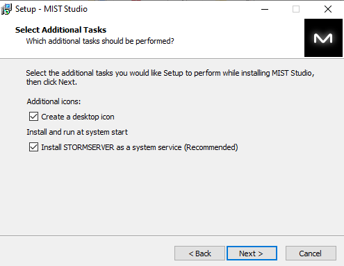
2.4.1. STORMSERVER service
![]()
When installing MIST Studio, STORMSERVER is also installed as a system service.
STORMSERVER is the engine used by MIST Studio for Background rendering.
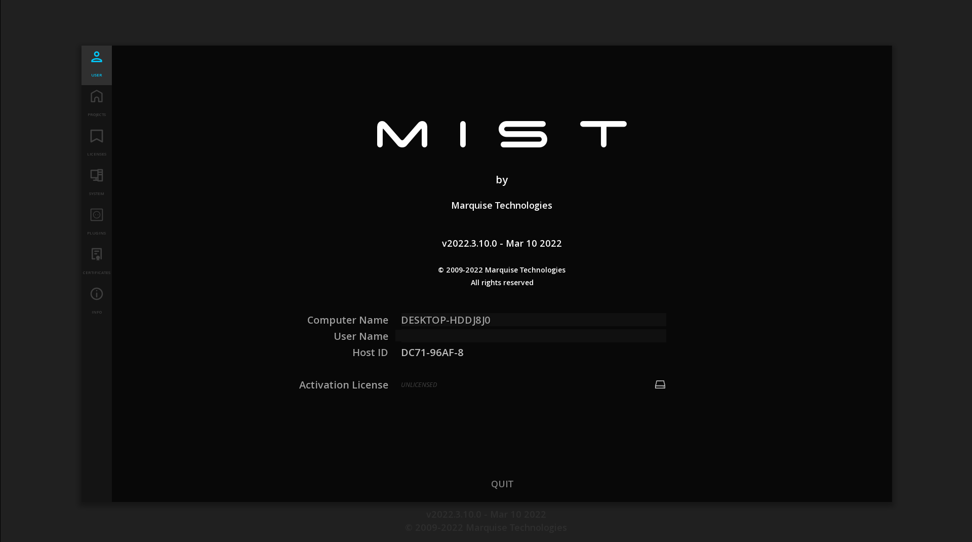
2.5. Starting MIST
On opening, the System module is displayed.
If it is the first time you launch MIST, it opens on the System / User page:
For all further openings, MIST opens by default on the System / Project Manager page.
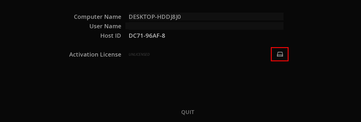
2.6. License installation
Launch the software to install the license.
From support@marquise-tech.com , you should have received a license file: license.dat.
Sometimes, for a special purpose, this file has a different name, you just need to rename it like this.
→ To import the license, click on the Browse icon:
→ Browse the file system to the location where you have stored the license.
By default MIST browser filters the files to only display ".dat" files in order to ease the search:
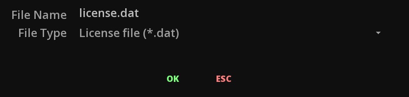
→ Validate with OK
Once the License has been successfully installed, the License Status displays the type of license:

3. GETTING STARTED
This Section covers high level information about MIST, and in particular:
-
MIST User Interface Structure
-
Overview of MIST Modules
-
Interface Basics
3.1. Software Organization
MIST is built around the Project TimeLine. This backbone is the principal module, from where all the features to achieve a specific job (mastering, versioning, QC) are accessible, as well as the settings for the project.
Another module is the System Module, the entry point to access all system-level settings and manage your projects.
3.2. Overview of the System Module
The System Module is the first module to appear when starting MIST.
In this module are set the parameters for the system, that will be valid for all the projects.
This is also the place where you can set user interface preferences or add a control panel.
This module is detailed under the chapter System Settings.
3.3. Overview of the Project TimeLine Module
In MIST everything must be done inside a project. However, unlike other software products, a project is not just a file that you load or save. In MIST a project designates a whole structure of directories and files that all together make up the project. The project can be then regarded as a shell for various objects that you work with or work on.
The general hierarchy of a project is based on various key elements that are used while working on a project. These elements are listed in the table below:
| Project settings |
Parameters that define the project at the top level such as default composition settings, user interface settings, video IO settings, etc. |
| Project media bin |
The Project media bin references media before it can be used in a composition. It is accessible from the Media tab of the the Command Panel. |
| Compositions |
Each composition is an actual timeline containing any type of assets: video, audio, timed text etc. Any media editing and image processing will be done within a composition. |
| Various metadata |
Other metadata stored in the project. |
The TimeLine is the backbone of MIST. From there all the necessary tools such as editing, conforming, primary color grading, calibration, color analysis and playback functions are available.
This is also from this module that you access all the mastering capabilities and export of deliverables.
The TimeLine Module workspace is composed of different elements:
-
The Menu Bar
-
The Command Panel
-
The Image Viewport
-
The Timeline
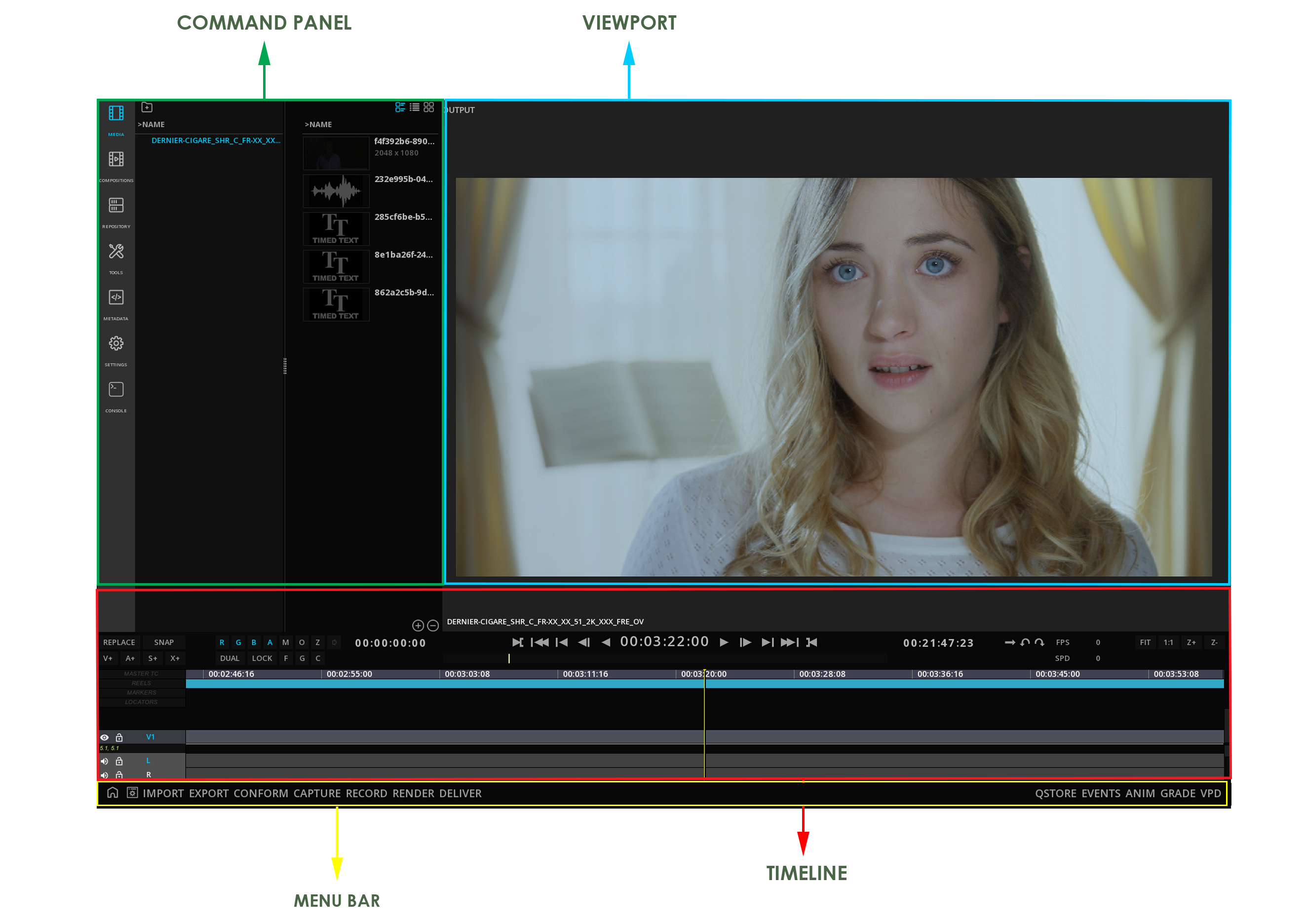
3.3.1. The Menu bar

This menu bar gives access to various capabilities of MIST, related to content management or specific features.
Content management
|
HOME |
Access to System Module / Exit the Project |
|
PROJECT SETTINGS |
Access to the Settings for the Project |
IMPORT |
Import metadata files (EDL, cutting list, color decision list, QC report, etc.), as well as content packages (DCP, IMF) and KDMs. |
|
EXPORT |
Export metadata files (EDL, cutting list, etc.) and reports |
|
CONFORM |
Access the Conforming panel |
|
CAPTURE |
Access the video Capture panel |
|
RECORD |
Access the video Record panel |
|
RENDER |
Display Render Queue |
|
DELIVER |
Create Masters according to delivery specifications |
Features
QSTORE |
Show / hide the QuickStore panel |
|
EVENTS |
Show / hide the Events Viewer |
|
ANIM |
Show / hide the Animation panel |
|
GRADE |
Access to Color Grading |
|
VPD |
Access to Video Pipeline Diagram |
3.3.2. The Command Panel
The Command Panel gives access to the assets of a project (media, compositions, metadata) as well as some tools for working with those assets.
From there you will also be able to import and manage the media for the project.
Accessing the Command Panel
By default on opening of a new project the Command Panel is displayed.
You can hide it using the icon ![]() COMMAND below the panel itself:
COMMAND below the panel itself:

Command Panel Menu
On the left of the panel a vertical menu bar gives access to the different features and tools :
|
MEDIA |
manage MEDIA of the project |
|
COMPOSITIONS |
display the different compositions of the project |
|
TOOLS |
access VIDEO ROUTING, AUDIO ROUTING, REELS,MARKERS, SUBTITLES and LOCATORS controls, QC REPORTS, ZEBRA Modes |
|
METADATA |
display assets and compositions' metadata |
|
COMPOSITION SETTINGS |
manage the COMPOSITION SETTINGS: Output format, color management, overlays |
|
CONSOLE |
provides information related to Storage, GPU and video IO card performances. See section CONSOLE |
3.3.3. The Image Viewport
The Viewport layout and capabilities are detailed in the chapter VIEWPORT
3.3.4. The Timeline
The TimeLine behavior is detailed in the chapter TIMELINE.
3.4. Interface Basics
Whatever the module or sub-module you are in, the following interface displays can be met.
3.4.1. Cursors
MIST mouse cursor changes appearance if an action with the mouse is possible:
|
Cursor in normal mode |
|
Possibility to move horizontally an interface element |
|
Possibility to move vertically an interface element |
|
Possibility to extend or resize and interface element |
|
Cursor in move mode |
|
Possibility to set an IN point (in the timeline) |
|
Possibility to set an OUT point (in the timeline) or to extend a clip duration (from the last frame of the clip) |
|
Cursor in trim mode |
|
Indicates that the application is busy performing an operation |


3.4.2. Settings Panels
In the System module or the Timeline modules, different panels are available. They are all have the same behavior:
| OK |
Validate the choices and eventually launch the operations |
| ESC |
Cancel an operation |
| EXIT |
Used to leave the panel |
| QUIT |
Quit the application |
3.4.3. Contextual Menus
A contextual menu is a menu in a graphical user interface (GUI) that appears upon user interaction, such as a right-click. This menu offer a selected set of choices that are available in the current state, or context, of the application.
The Contextual Menus are accessible from every module of MIST, at the current mouse cursor location.
|
Calling a contextual menu when mouse cursor is located on a specific panel or interface element is not always possible. In that particular case, move the cursor to the nearest empty part of the user interface to be able to call the desired Menu. |
MIST uses Drop-down Menus for contextual menus.
The drop-down menus give quick access to possible actions for the specific area the mouse is located.

3.4.4. Hot Boxes
Hot boxes are available on certain part of the user interfaces, allowing a quick access to tools related to the timeline for example.
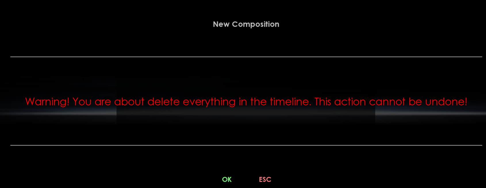
3.4.5. Warning Messages
Warning messages can appear in the different modules of MIST.
These messages interrupt the current work, in order to inform the user about a critical path.
Warning messages always require an action from the user : press [OK] to continue or ESC to cancel.
3.4.6. Keyboard Shortcuts - Help
A lot of keyboard shortcuts are available in MIST.
-
Press the keyboard H key to display the Shortcuts List available for the current Module (available from the Library module and the TimeLine module)
A recapitulation of the available Keyboards Shortcuts for MIST is available in Appendix Keyboard Shortcuts. Animation</a> panel
4. SYSTEM MODULE
The System Module allows the settings of different parameters for the system, and allows the management of the Projects.
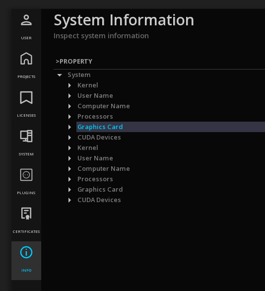
4.1. User
In the User page you will find important information like
-
the current version of MIST
-
the type of MIST License installed
-
Computer and user name information

4.2. Projects
This is the page where you can manage and access all your projects.

Once the license has been installed, the software will always open by default on the Projects page.
4.2.1. Creating a New Project
→ To create a new project, type a name in the Name field and validate with CREATE:
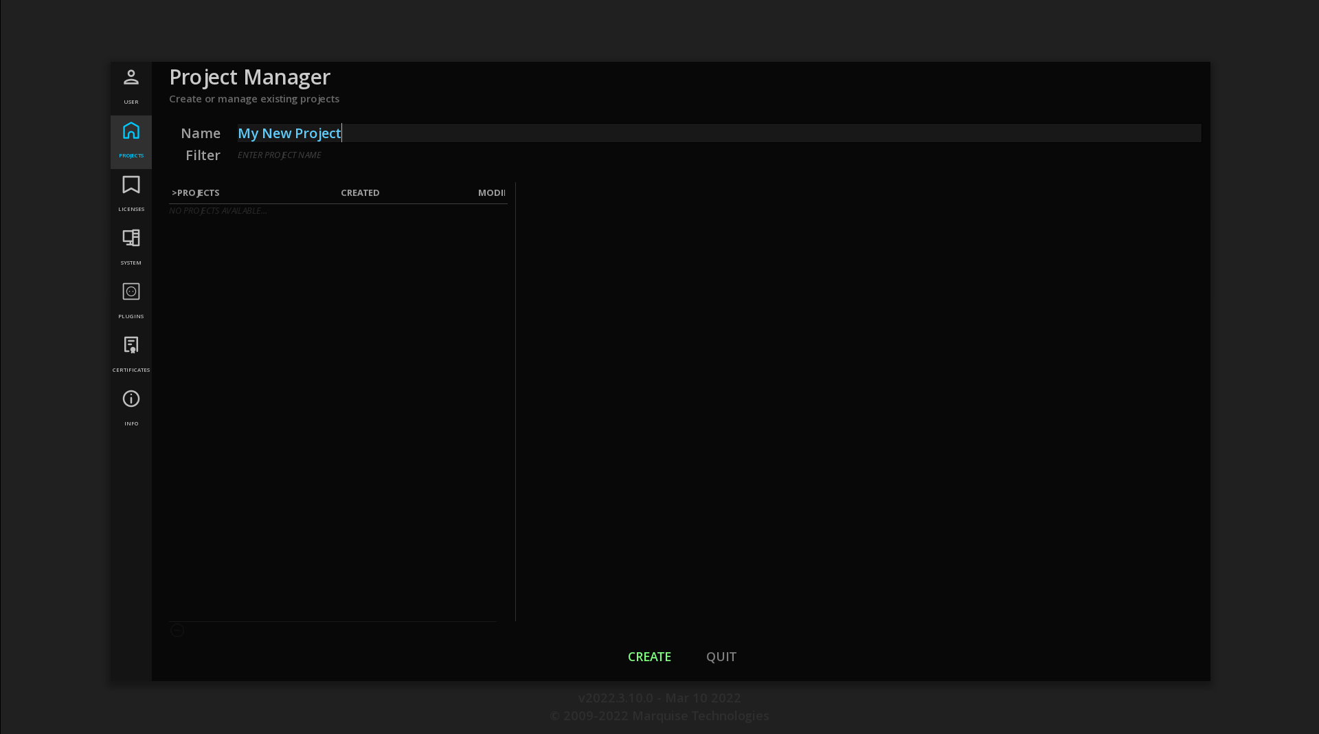
|
The following characters are forbidden: |
4.2.2. Opening an existing Project
On the left column the list of all the projects is displayed.
On the right column you find the list of all the compositions saved for the selected project.
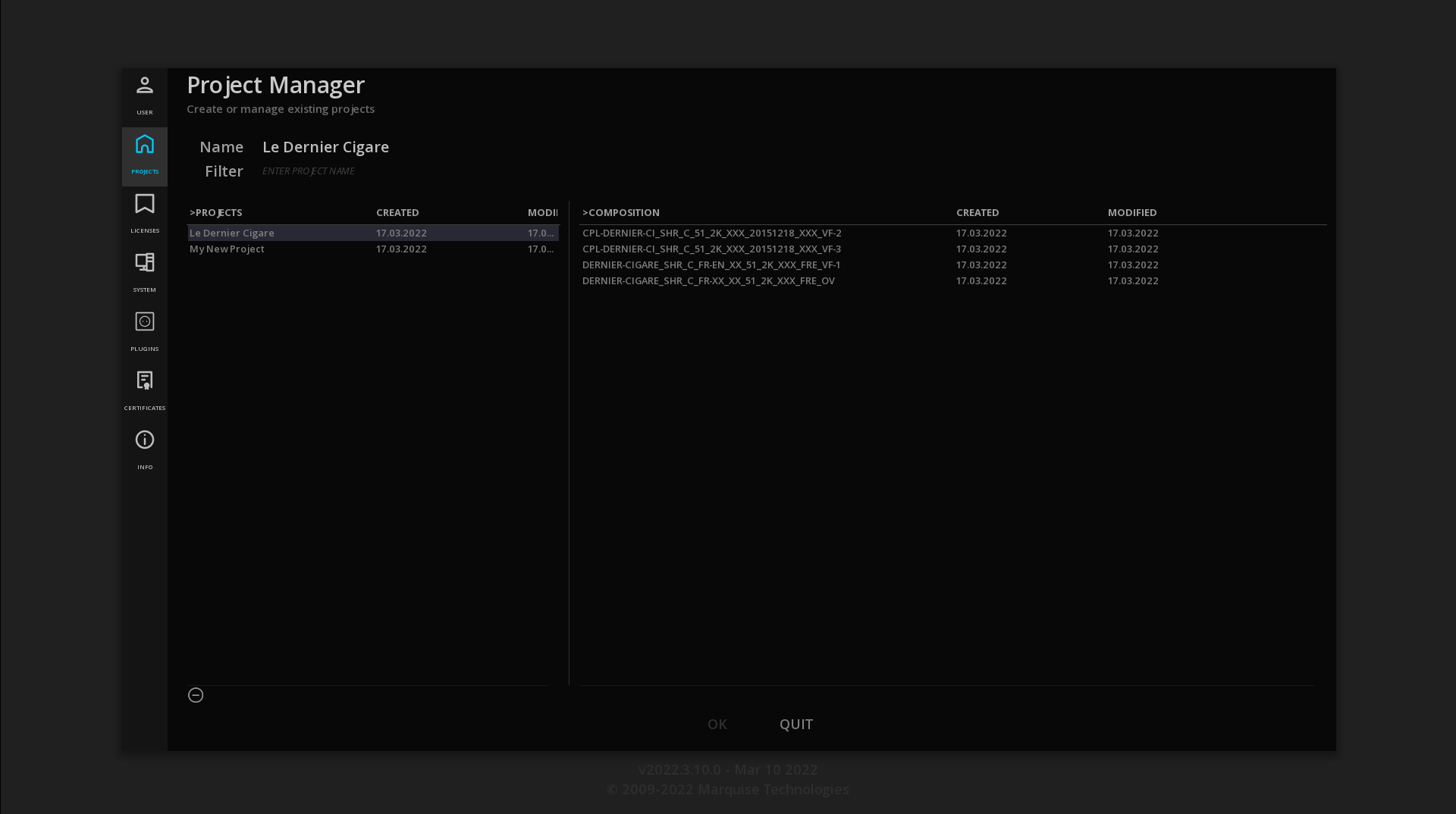
→ Select the project or the composition directly and click [OK].
→ A double-click on the project will open the last saved composition.
You can also sort the Projects and their Compositions by Date Created or Date Modified:
→ Click on the column title to sort the list.
→ Click again to toggle Ascendant/Descendant order.
You can filter the projects to display only Project names containing a certain text:
→ In the Filter field, type the desired text
4.4. System
In this page you can configure your system parameters.
| Codecs |
Set the decoding and encoding parameters for JPEG2000 |
| Control Surface |
Connect and setup an existing control surface. |
| Mastering Display |
Setup the communication with the Reference Monitor. |
| Dolby |
Setup the properties for Dolby Atmos and Dolby Vision. |
| Nexguard |
Configure an existing Nexguard account. |
| TORNADO |
Configure a TORNADO server for MIST. |
4.4.1. Codecs
This tab allows you to set the parameters when working with JPEG2000. Depending on the performances of your workstation you can choose to use CPU or GPU power.
In CPU mode, you can also defines the maximum number of CPU threads engaged in the encoding or decoding process.
|
CPU encoding: the number of threads varies with the available shared memory. |
4.4.2. Control Surface
When using a control panel, this is where you can connect and configure it.
The Tangent Devices panels are supported.
→ Select Tangent Tube from the drop-down menu.
|
Please be sure to have install the control panel’s drivers before. |
4.4.3. Mastering Display
This tab allows you to configure the communication between your Reference monitor and the application: the ST-2086 metadata selected in the Mastering Display of the COMPOSITION SETTINGS can be automatically sent to the Reference monitor, allowing to configure it accordingly and avoid the operator to use the monitor’s manual menu.
The following monitors can be remote controlled:
-
Canon HDR 4K monitors
-
Eizo HDR 4K monitors
-
TVLogic HDR 4K monitors
Eizo CG-3145 PROMINENCE
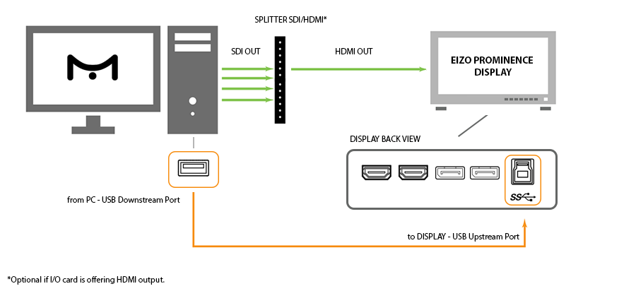
To physically establish the communication between a EIZO Prominence monitor and your workstation, you need to connect a USB cable between the USB downstream port of the PC and the USB upstream port of the monitor before launching the software. The USB hub function is set up automatically upon connection of the USB cable.
When the application is launched, it takes control of the settings of the EIZO monitor. Each time a composition is loaded, the selected mastering display parameters are communicated to the EIZO monitor, which is automatically configured accordingly.
A change of mastering display preset will refresh the monitor. The new parameters used are indicated temporarily on the monitor.
TVLogic LUM-310R
To establish the communication between a TVLogic LUM-310R monitor and your workstation:
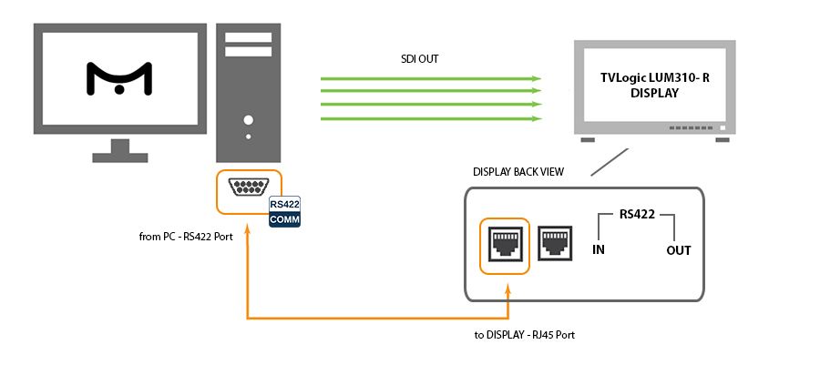
-
Get a DB9 Female to RJ45 Male cable.
-
Connect the cable from the RS-232 port of your computer to the RS-422 IN port of the TVLogic display.
-
Open the
.cfgfile for your application in the directory C:\Users\$SessionName$\AppData\Roaming\Marquise Technologies\session. -
Add the following lines between <MTSessionConfig> and the </MTSessionConfig> tag:
<DisplayMonitorConfigList>
    <DisplayMonitorConfig id="tvlogic">
        <CommPort>COM1</CommPort>
        <DeviceId>1</DeviceId>
    </DisplayMonitorConfig>
</DisplayMonitorConfigList>
The CommPort number to indicate depends on the CommPort available on your system.
The DeviceId number must be the same as indicated in the monitor’s menu settings in the GPI tab / Monitor ID. Change one or the other accordingly. The default DeviceId is number 1.
Save the file before leaving.
4.4.5. TORNADO
TORNADO is a transcoding server that can be linked to MIST in order to offload the rendering from MIST PC system.
-
set the url of the server TORNADO has been installed on.
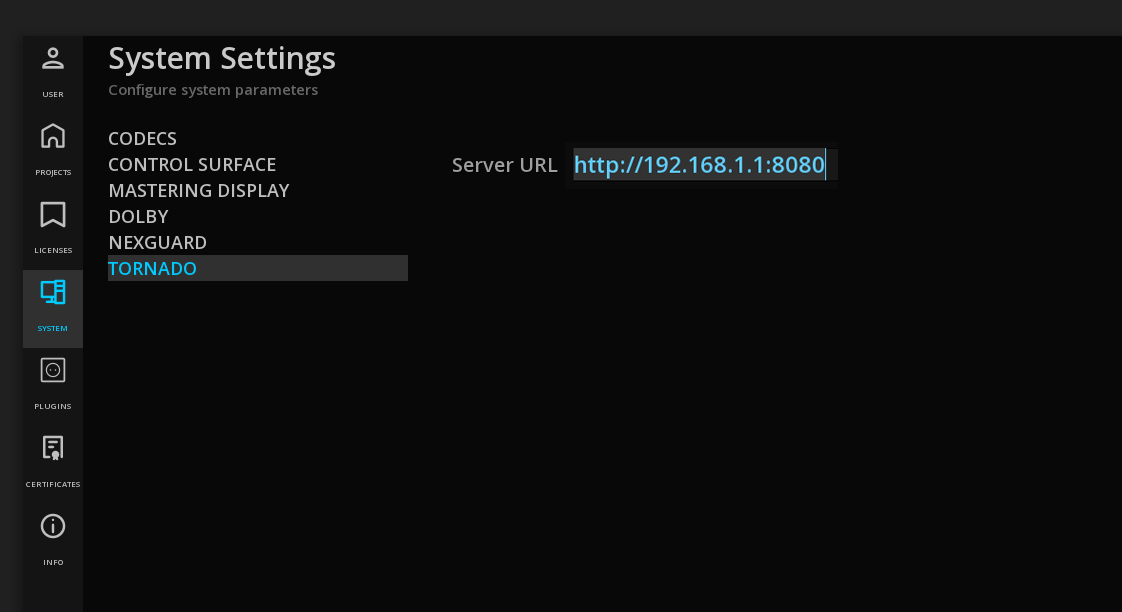
Read more on TORNADO : https://marquise-tech.cloud/portal/en/kb/articles/tornado-user-guide
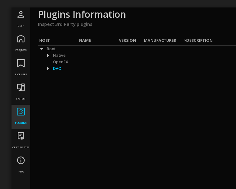
4.5. Plugins
This page displays the plugins (options) that are currently installed with your version of MIST:
5. PROJECT SETTINGS
Project Settings are accessible from the Project Timeline.
→ To modify the Project settings, use the ![]() Project Settings icon in the menu bar of the TimeLine or press F1.
Project Settings icon in the menu bar of the TimeLine or press F1.
The Project Manager appears in a panel, composed of different tabs:
| General |
General information of the project (e.g. Production company, EIDR, ISAN etc) |
| Properties |
Set the properties and type of the project. |
| Media |
Manage the default media settings. |
| Video Output |
Configure the video output settings of the Video I/O board (e.g. Bluefish444 or AJA). |
| User Interface |
Set user interface preferences. |
| Cache |
Manage the cache. |
| Misc |
All the miscellaneous settings like the auto-save setting. |
| Dolby |
Setup the properties of the CMU device. |
| VTR Emulation |
Configure settings to turn MIST in a virtual telecine. |
| Reports |
Specify a default location when exporting the different Reports. |
To leave the Project settings, click EXIT to go back to the TimeLine.
|
You can modify the Project settings at anytime. The settings chosen will not affect the project’s compositions, it will only assign defaults parameters to the new compositions created. |
5.1. General Settings
For all projects, it is possible to enter additional information or metadata that can be used as reference information to identify a project:
Insert custom information like Production Company, Director’s name, etc.
→ Click on the edit field and type desired information.
When present, these metadata will be avaialble in the overlays or the naming convention.
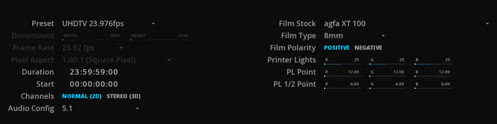
5.2. Properties
In the Properties tab, set the default dimensions, frame rate or duration for all new compositions in the project.
Each new Composition of the project will be created with these parameters.
|
The settings of a particular composition can be modified at any time, see Composition Settings chapter. |
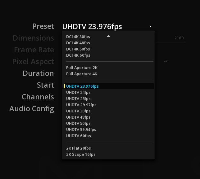
Preset
There is is different output format available as presets:
→ Select the desired preset to set automatically the dimensions, the frame rates and the pixel aspect of the media.
Custom Output format
To define a custom format, select Custom in the Preset drop-down menu, and enter the desired format, frame rate and pixel aspect:
Dimensions
→ Click on the width digits to edit the text and enter the desired value.
→ Press tab to edit the height digits.
→ Finish with enter to save the new dimensions.
You can also change the dimensions by navigating in the cyan bar by dragging the slider one way or the other.
Frame rate
Choose if the project will be played in 24, 25, 29.97 or 30 frames per second. It is important to bear in mind the destination of the final result when setting the frame rate, as it will affect the playback speed.

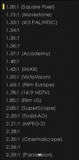
Pixel Aspect
Select the desired aspect ratio of the Custom project size: 4/3, 16/9, or any other ratio from 1.00:1 to 4.00:1.
Duration
By default, the composition duration is set on 24h.
→ To change the project composition duration, click on the edit field and enter the desired composition duration for the project.
Start
It is possible to set the beginning of the composition (the start) at a specific TimeCode.
By default, the Start is set on 00:00:00:00.
|
This setting affects the current composition only. To modify the Start TC for all new compositions in the project, see Default Start. |
Channels
→ Choose if your project is a Stereo3D project or a normal 2D one. By default, the project is set in Normnal 2D.
Audio config
Allows you to choose a default audio configuration for all new compositions in the project.
Digital Intermediate settings
The following settings are useful only when working from film stock.
Film Stock
If you are working from film then select the stock type via the drop-down menu.
Film Type
Setting a Film type will define how the TimeLine is calculated in Feet + Frames (please refer to the chapter Changing the Timebase display).
Available film types are: 8mm and super 8mm, 16mm, 35mm (2, 3, 4 or 8 perforations) and 65mm (5, 8, 12 or 15 perforations).
Film Polarity
Click on the film polarity in use. The selected one is highlighted in cyan.
Printer Lights
Set the printer to obtain balance for color and density of the stock film. PL Point and PL 1/2 Point allow to refine the values more accurately.
5.3. Media
Media Directory
The Media Directory allows to define a default location for all media for this project.
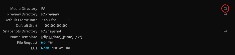
Preview Directory
Choose where to store the video thumbnails (media preview) automatically generated when a video content is referenced in a project. By default, they are stored in the Project directory.
Default frame rate
Some image sequences (e.g. DPX) do not carry frame rate information. In such cases, it is necessary to define a frame rate for this content.
|
Choose a frame rate from the drop-down menu for your image sequence before importing media into the library. |
5.4. Video Output
In this panel, you can define the output signal. Select it from the drop down menu.
| None |
The ouptut signal will be sent from the NVIDIA GPU |
| IO board |
The output signal will be sent from the video IO board installed |
| NDI |
The output signal will be sent to a NDI connected device. |
Video IO boards
If a video IO board is properly installed, its name will be displayed in clear in the drop down list and you can start setup the video output of your project.
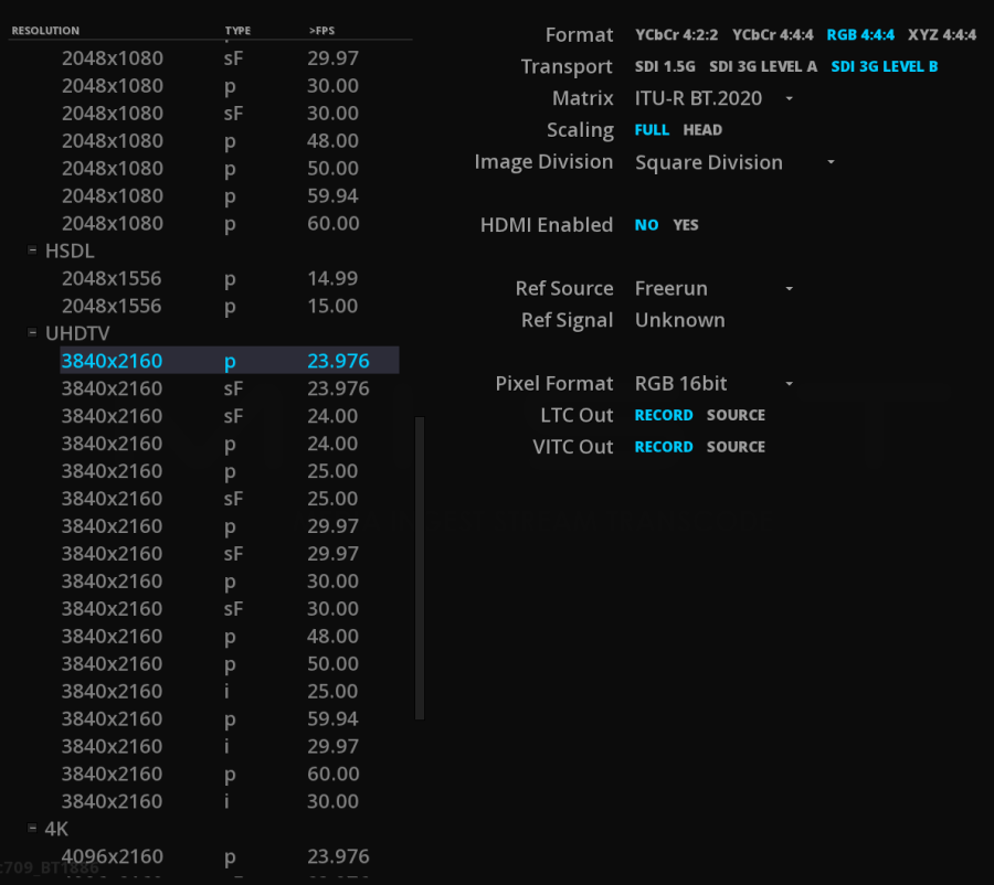
|
Resolutions displayed in the list are relative to the formats supported and delivered by the I/O card. Basics drivers are installed with the application. The |
|
The Video output settings of the Project only defines the output through the video IO card. |
HDMI
When available from the video IO board, selecting this option output the signal using HDMI as well.
Both SDI and HDMI output can be done in parallel.
Dolby Vision
Enable this option to send the Dolby Vision metadata over HDMI to the consummer TV (tunneling). See Dolby Vision for more information.
|
The Dolby Vision Tunneling capabilities is only available using a AJA Kona 5 video IO board. |
Audio Delay
The audio delay is used to read the audio ahead of the video in order to compensate the delay introduced by an external audio processing device (e.g. a Dolby E decoder).
The value represents the number of frames ahead of the video position from which audio is read during playback.
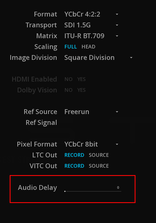
→ Use the slider or double-clik on the value to set the desired audio delay in frames.
|
This option only affects playback, not rendering |
5.5. User interface
Select your preferences for the user interface:
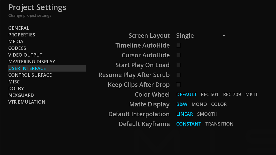
| Screen Layout |
Allows you to display the User Interface on 1 or 2 monitors (Dual). |
|
you must restart the software to apply this change. |
| Timeline Auto-Hide |
automatically hides the Timeline during playback |
| Cursor Auto-Hide |
automatically hides the mouse cursor during playback |
| Start play on Load |
starts automatically the playback of the content loaded on the timeline. |
| Resume Play after Scrub |
resumes the playback after a scrub of the playhead with the mouse. |
| Keep Clips after Drops |
keeps the clips attached to the mouse when performing a Drag and Drop on the timeline. This is useful when adding the same clip several times on the timeline. |
| Color Wheel |
Allows you to choose the orientation of your color-grading wheels |
| Default Keyframe |
Selects the default Keyframe and interpolation settings based on your needs. |
5.6. Control Surface
When using a control panel, this is where you can connect and configure it.
The Tangent Devices panels are supported.
→ Select the desired device from the drop-down menu.
|
Please be sure to have install the control panel’s drivers before. |
6. IMPORTING MEDIA
MIST allows to import a large variety of media:
flat files, packages like DCP, IMF or iTunes, image sequences, PDF and XML files in sidecar, EDLs, camera magazines, etc.
In MIST, media are managed in the Media tab of the Command Panel.
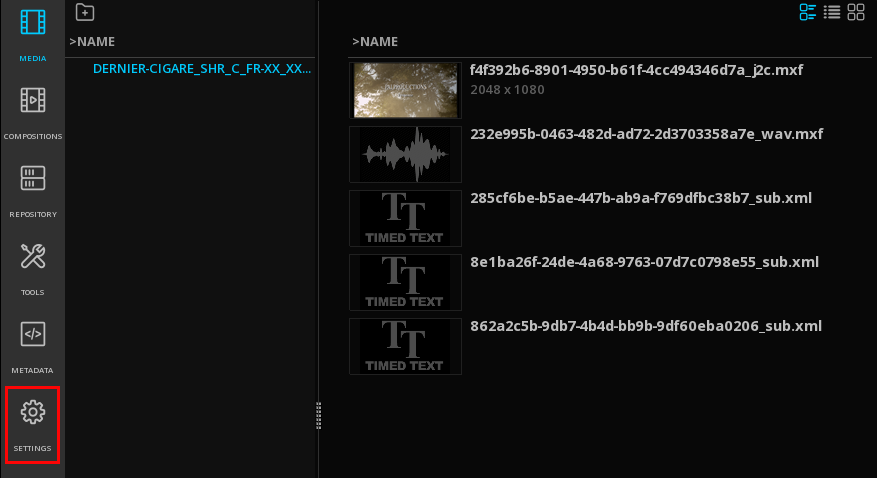
6.1. Media Tab
The Media tab is where the essences for a specific project are manually or automatically referenced from disks or a SAN.
The essences can be any type of video, audio, or subtitles files.
The Media Tab also permits the organization of the content for a project. From there assets can be selected to get loaded on the timeline.
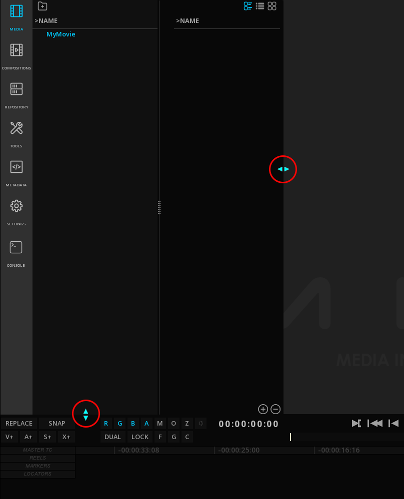
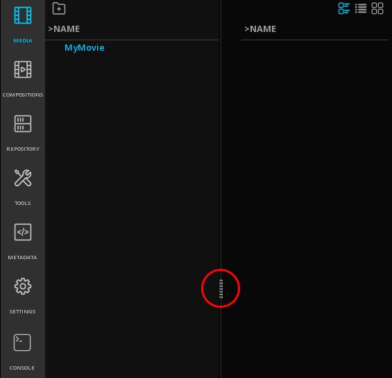
The MEDIA tab is composed of 2 columns: on the left, the folder tree, and on the right the related content, like in a standard file browser interface.
→ To adjust the width of the columns use the vertical slider :
6.1.1. Organizing the Project Media
Folders
You can create folders to organize the project media according to your needs.
→ to add a folder, position the mouse in the left column and right-click. Choose New from the drop-down menu:
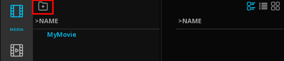
Alternatively you can use the icon "create new folder":
|
when adding other folders at root level, make sure that the root project is selected (highlighted in blue) and not a folder. |
→ to add a sub-folder, select the desired folder and right-click on it. Choose New from the drop-down menu:
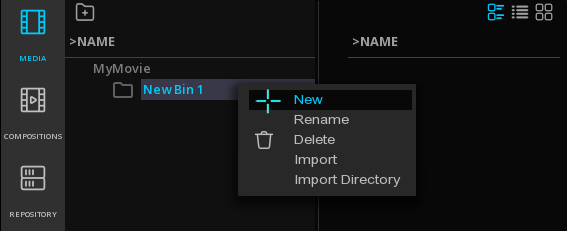
Alternatively you can use the icon "create new folder".
→ to delete a folder or a sub-folder, select the desired folder and right-click on it. Choose Delete from the drop-down menu.
→ to rename a folder or a sub-folder, select the desired folder and right-click on it. Choose Rename from the drop-down menu.
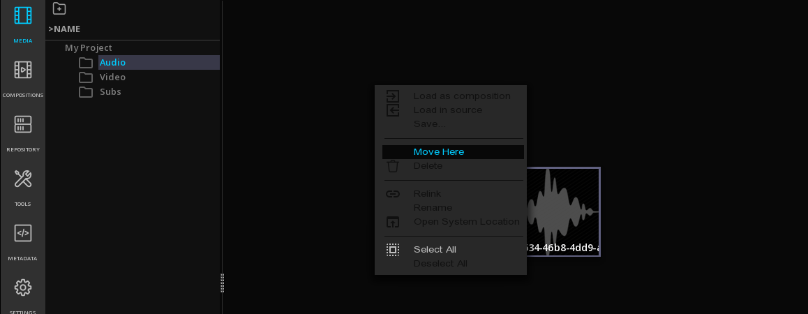
Moving media
You can rearrange the media in the folders once they have been imported in the Media bin:
→ Using the mouse, click on the media then lift it with a quick swipe of the left mouse button. This process is called Lift, Carry & Drop. The Clip will be attached to the mouse.
→ Select the new folder location:
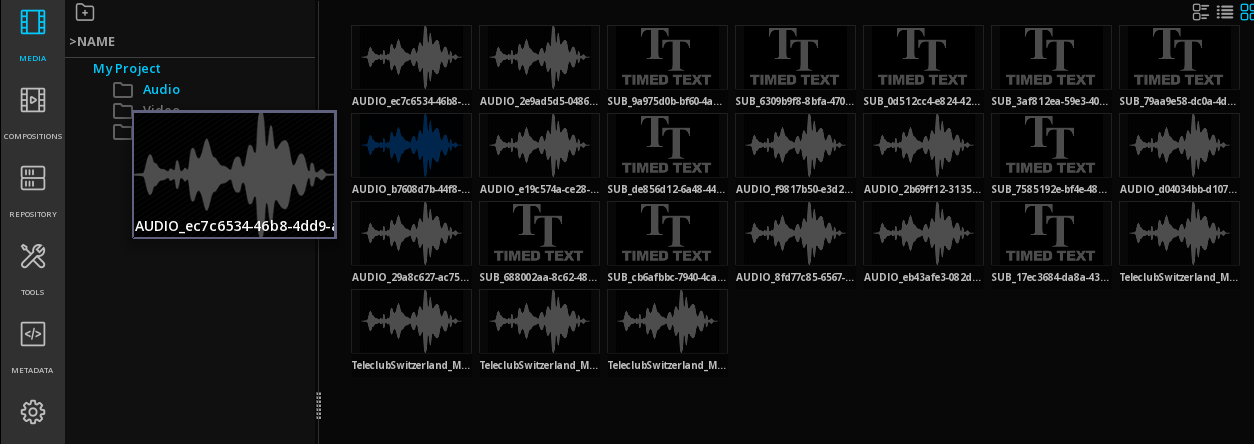
→ In the folder bin, use right-click and select Move Here:
6.2. Import of Media
There is two ways for importing media for a project:
-
Drag & Drop from Windows file system
-
Import function using the internal smart file browser
6.2.1. Drag & Drop files from Windows' file system
Drag & Drop from Windows' file system allows you to easily import flat files, packages (DCP, IMF, iTunes, etc..), image sequences, compositions, sidecars files, etc.
→ Hit the Windows key or press + at the bottom right of the panel to display the Windows file browser.

→ Select your files and drop them anywhere in the application’s window.
Once the media are properly referenced, they are displayed in the Media tab.
→ To import content into a specific folder of the project media, first select the desired folder prior to drag & drop the content.
Drag & Drop sequences
To import image sequences like DPX or TIFF drag & drop the first image of the sequence and the full sequence will be automatically imported.
|
Because there is no information about frame rates in DPX or TIFF images, first set the correct frame rate in the Properties of the Project. |
6.2.2. Import Panel
The Import panel is an internal smart file browser that has the capability of understanding complex media files and packages.
Access import from the Media tab
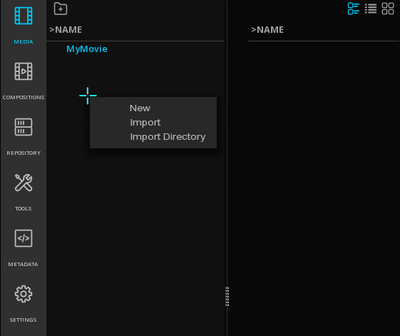
→ position the mouse in the left column and right-click. Choose Import from the drop-down menu:
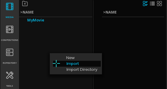
→ Alternatively double-click on an empty area of the left column
→ To import content into a specific folder of the project media, first select the desired folder prior to import the content.
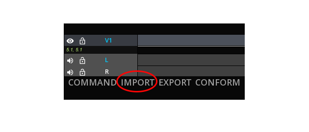
Access from the IMPORT button
Click on the IMPORT button on the menu bar to display the Import panel.
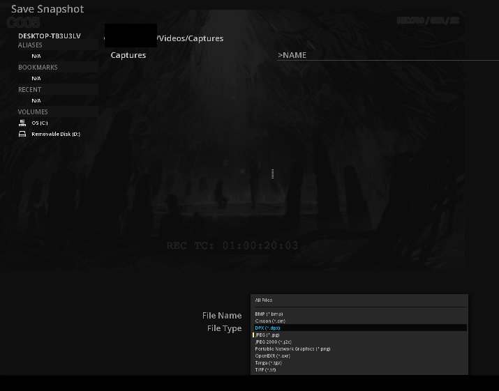
Import panel
The Import panel is composed of 2 areas:
The left column, used for quickly navigating through the physical files volumes the system is connected to.
Bookmarks and Aliases are also displayed there.
The folder tree column, showing folders' organization within a volume.
In order to ease the navigation, you can display only a specific file type.
→ Click on the file type to open the drop-down menu:
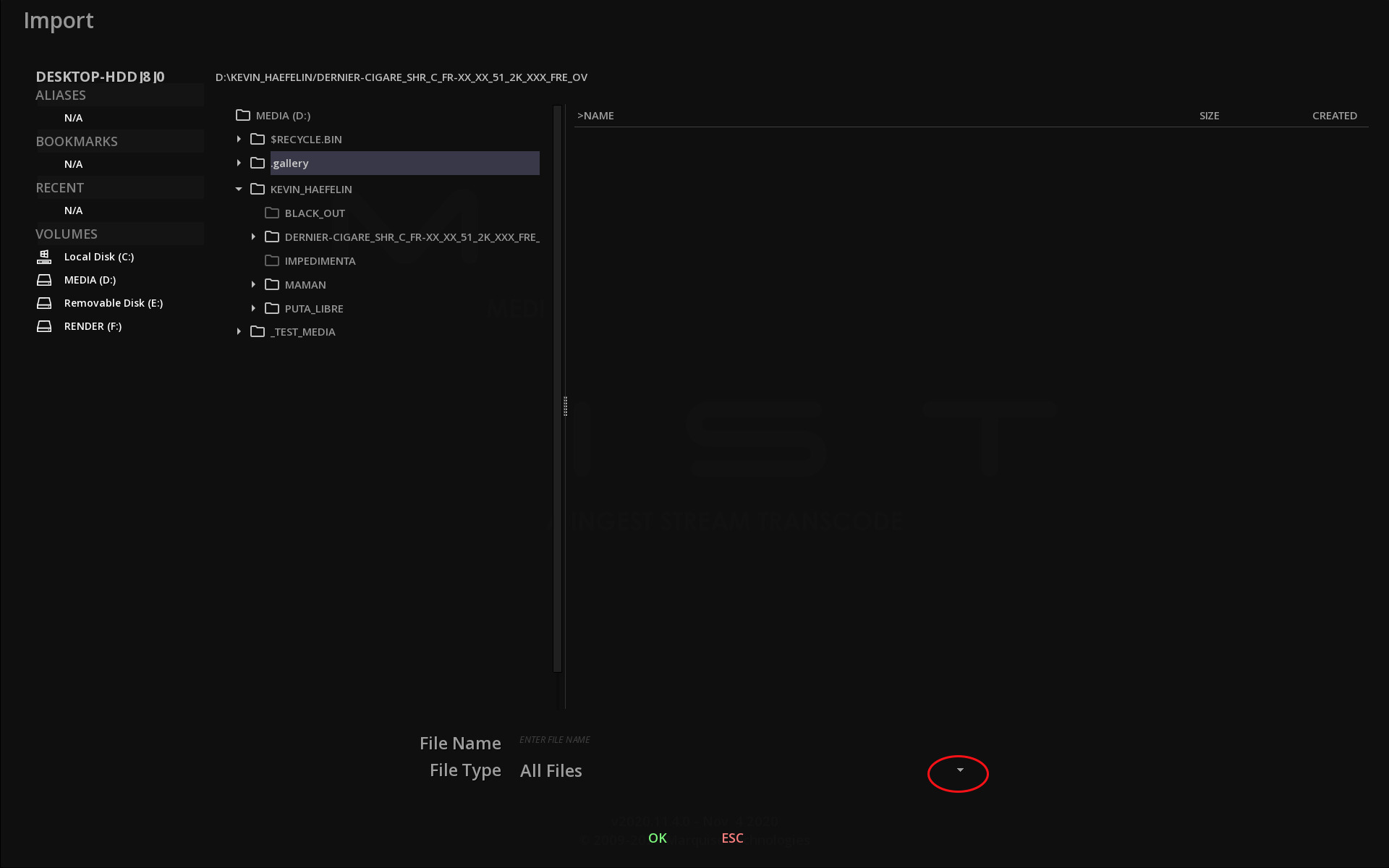
→ Select the desired type of file from the list:
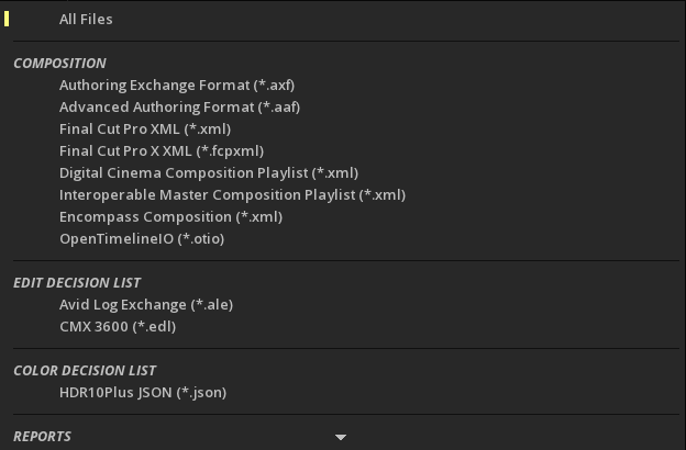
→ Validate the import using OK.
6.2.3. Delete Media
→ To delete a media, select the desired clip and press *- at the bottom right of the Command Panel.
→ Alternatively, when the clip is selected, you can →. Choose Delete from the drop-down menu.
|
Deleting a media in the Media tab will remove it from the Project media bin and will not physically delete the file. |
6.2.4. Import of Directory
It is possible to import an entire directory in the project media bin: the source directory organization with the folders and subfolders and their related files is reproduced in the media bin.
This functionality is particularly useful when importing complex folder’s organization like a camera magazine or DPX sequences organized in reels.
→ To import a Directory, position the mouse in the left column and press mouse’s right button. Choose Import Directory from the drop-down menu:

Navigate in the file browser to the desired directory, and validate the import using OK.
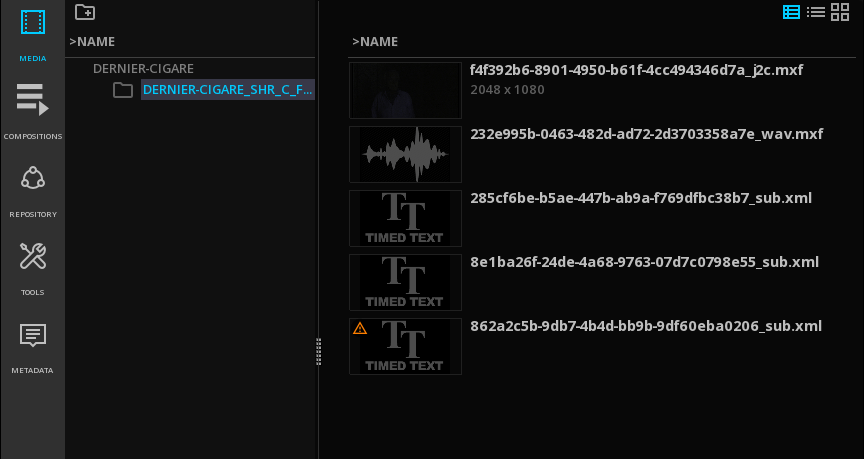
6.2.5. Media views
The operator can display the media assets using different views :
-
Thumbnails
-
List details
-
List tiles
Click on the View icons on the upper right of the Command Panel to change the views:
6.2.6. Encrypted content
When importing an encrypted DCP, the assets are displayed with a closed lock and the media preview is black:
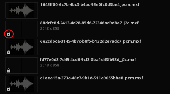
After importing the KDM (See Import Encrypted DCP), the locks are open and the media preview is enabled.

6.3. Media tab Options
6.3.1. Direct PlayBack
→ A double click on a media will automatically load the content on the timeline.
→ To start automatically the playback of the content loaded on the timeline, enables the option Start play on Load in the Project Settings, User interface.
→ To load manually the media on the timeline, refers to section Adding clips to a composition.
→ to start the playback of an IMF or DCP package, see the Composition tab information on next chapter.
6.3.2. Media tab Menu
When performing a right-click on a clip in the Media bin you access the Clip menu offering several options:
| Load as Composition |
Load the clip on the timeline in a new Composition |
| Load in Source |
Load the clip in the Source Viewport |
| Delete |
Delete the clip from the project media bin |
| Relink |
To relink a media |
| Rename |
Rename the file as it appears in the media bin. Does not affect the name of the original file. |
| Open System Location |
Opens the Windows’s file browser to the physical location of the media |
| Select All |
Select all the clips in the current directory |
| Deselect All |
Deselect all the clips in the current directory |
| Add Media Track |
Add the media as an additional track on the current composition |
| Export as… |
Allows a quick conversion of an audio or a subtitle file. See Export of an essence file. |
| Validate… |
Opens the Validation panel. See Master Validation. |
| Deliver… |
Shortcut to Master Delivery Panel. This is useful to quickly transcode a flat file as is, without adding it on a timeline to create a composition. See Master Delivery. |
| Rewrap… |
Offers a choice of rewrapping the media in all possible formats according to the codec parameters. See also Rewrapping. |
| Save Media Info report |
Create a media info report in PDF and XML as well as in EBUCore XML. |
6.3.3. Adding separate audio or subtitles files
In order to playback stand alone files together with a video, for example external subtitles or audio files, it is possible to add them on the current timeline:
→ Right-click on the file and select Add Media Track: a new track with has been created.
|
The new clip is placed at the position of the playhead. |
6.3.4. Relink Media
When a media referenced in a project has been moved from its original physical location, the application cannot access it and it is no longer possible to work with it.
In this case, a warning is displayed on the clip:
It is then necessary to proceed to a manual relink of the path to the files.
-
right-click on the clip in the Media tab to display the drop-down menu.
-
Browse the file system to the new location of the file
-
Click OK to validate
Your media is now relinked.
6.4. Compositions Tab
This tab displays all the compositions available in the project, whatever their type is: CPLs of an IMF or a DCP package as well as project’s compositions.
6.4.1. Saving Compositions
By default, when a media imported in the Media bin is played directly, a Temporary composition is automatically created.
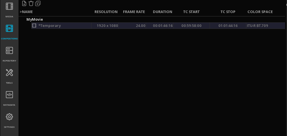
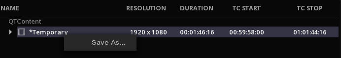
This composition will be replaced by a new temporary composition if another media is chosen to be played, unless it is manually saved.
→ To save a temporary Composition, right-click on it and enter a name in the text field:
→ Alternatively press Ctrl+S and type a name for the composition:
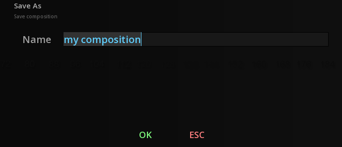
The new composition is then available in the list.

6.4.3. CPLs
When importing a DCP or an IMF package, CPLs are listed as compositions:
A tag IMF or DCP clearly identify them in the list.
|
If a change is made to an original IMF or DCP composition, the tag will disappear. |

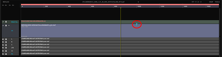
When a CPL refers additional matadata files, like Sidecar or OPLs, the Composition display a triangle:
→ Click on the triangle to expand the composition information
6.4.4. Playback of the Composition
→ A double click on a Composition will automatically load all the assets referenced in the composition on the timeline.
6.4.5. Toggle compositions in the project
When a project contains several compositions, you can quickly toggle from one to another:
→ To toggle between compositions, double click on the desired one: the timeline automatically switches compositions.
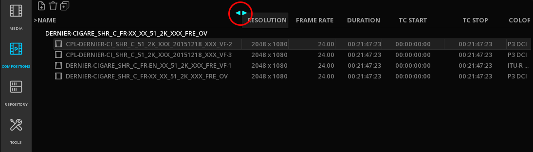
6.4.6. Adjust columns
You can modify the length of the columns for the list of composition. Position the mouse until the cursor changes appearance next to the column you want to modify and slide:
Read more on Compositions
6.5. Media Inspection
The Metadata Tab of the Command Panel allows the inspection of the metadata embedded in a file: COMPOSITION, CLIP, STATIC and DYNAMIC metadata.
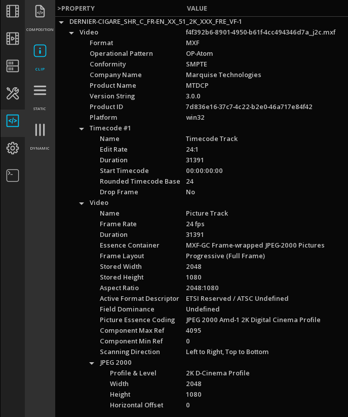
| COMPOSITION |
settings of the composition |
| CLIP |
thechnical metada of the clip |
| STATIC |
technical or descriptive metadata valid for the entire clip |
| DYNAMIC |
technical or descriptive metadata valid for a frame or a scene. |
|
The metadata displayed are those of the file loaded on the timeline. When multiple files are present, the metadata are displayed for the content on the active layers at the playhead location. |
|
To inspect the metadata of a clip in the media tab, without modifying the current composition on the timeline, you can load it in the Source Viewport. |
6.6. Media Metadata Exports
It is possible to export the metadata of a media file.
→ Right-click on a media in the Control Panel / MEDIA tab and choose Save Media Info report from the drop down menu to open the Media Metadata Export windows.
The Media Metadata Export windows opens.
In the file type, select the desired Metadata export:
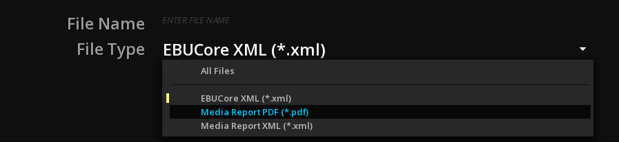
| EBUCore XML |
exports the media metadata in XML following EBUCore specification |
| Media Report |
exports a Media Report in PDF or XML format |
→ Add a name for the file and browse the file system to the desired location and validate with OK
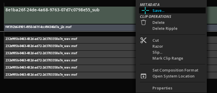
The Media Metadata Export windows can also be accessed from the timeline:
→ Right-click on the desired clip on the timeline and choose Save… from the drop down menu:
7. VIEWPORT
The Viewport is the part of the workspace where the image is displayed.
On opening of a project, the Viewport is reduced but you can enlarge it by closing the Command Panel or minimizing the timeline.
7.1. Navigate / Pan
To easily navigate in any area of the image, use the pan navigation:
→ Alt + click and maintain left mouse button pressed to move the image in every possible direction.
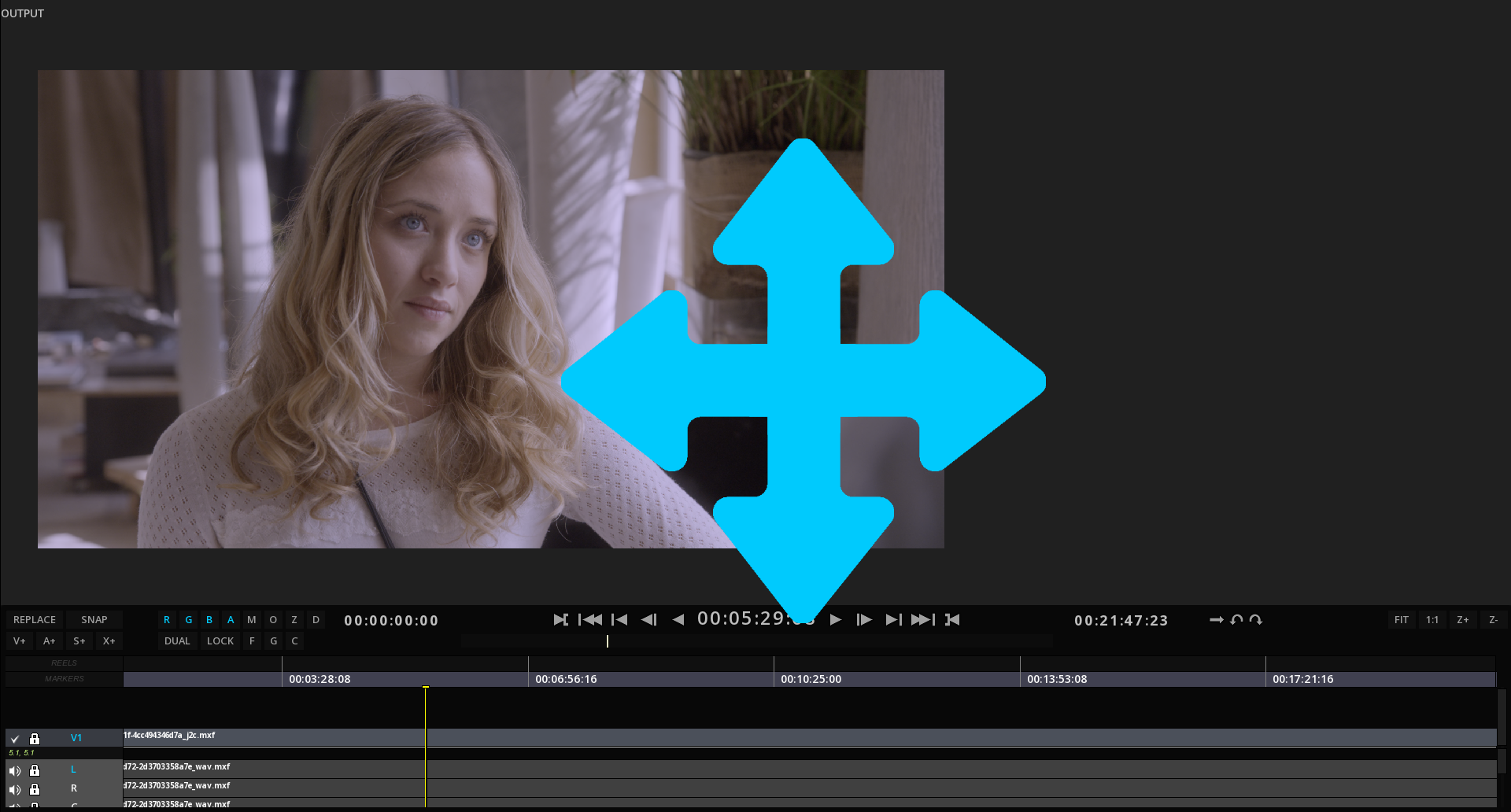
→ Press C to center the image in the Viewport.
7.2. Zoom
To zoom in a specific part of the image:
→ Scroll middle mouse button down to zoom IN, and scroll up to zoom OUT.
7.3. Viewport Options
7.3.1. From the GUI
Some controls for the Viewport are directly accessible from the GUI (in addition to keyboard shortcuts).
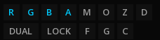
R |
Show / hide Red channel |
G |
Show / hide Green channel |
B |
Show / hide Blue channel |
A |
Show / hide Alpha channel |
M |
Show / hide Mask |
O |
Show / hide Original image |
Z |
Show / hide Zebra mode |
D |
Show / hide Dynamic Tone Mapping |
F |
Lock Fit Viewport |
G |
Gang the 2 Viewports |
C |
Comparator |
Dual |
Show / Hide Dual Viewport |
Lock |
Lock Viewports playback together |
7.3.2. Guides
Display guide lines on the Image Viewport:
| Camera |
Alt+C to show camera borders (project format) |
| Axis |
Alt+A to display the Viewport axis |
| Safe Frames |
Alt+F to show Action and Title safe areas according to the Active Area chosen. |
| Active Area |
Alt+B to display the borders of the frame as per the frame aspect chosen in the Active Area tab. |
7.4. Snapshots
It is possible to capture a snapshot of the content displayed in the viewport.
→ to capture a snapshot, press Ctrl+F12.
Settings for the snapshots are located in the Media section of the Project.
It is possible to define automatically the naming convention for your snapshots as well as the directory to save them, or to opt for a manual saving.
You can also add the LUT defined for the GUI or the SDI output.
7.5. Transport Controls
The commands for the Transport controls are the following:

1 |
Composition Start time |
2 |
Mark IN point |
3 |
Go back to first frame |
4 |
Go back last key frame |
5 |
Go back next frame |
6 |
Play backward |
7 |
Time Code at current frame / PlayHead position |
8 |
Play / Stop |
9 |
Go to next frame |
10 |
Go to next key frame |
11 |
Go to last frame |
12 |
Mark OUT point |
13 |
Composition End time |
14 |
7.6. Dual Viewport
The Dual Viewport allows you to display simultaneously two video tracks for comparison purposes. The two Viewports can also be synchronized together, for an accurate frame matching.
7.6.1. Adding media on the Dual Viewport
→ To open the Dual Viewport, click on DUAL on the TimeLine or use the shortcut Alt+X:

The Record Viewport (right) is for the Composition, and the Source Viewport (left) is used by the source media.
→ Select the source media from the Command Panel and press Ctrl + double mouse click: it will automatically be placed in the Source Viewport.
→ Alternatively, you can right-click on a media and choose Load in Source to directly open it in the Source Viewport.
→ From the Compositions list in the Command Panel you can also use right clik on a composition to choose Load in Source Viewport.
|
All kind of file formats can be loaded in the source viewport, including IMF and DCP packages. |
→ To toggle from one Viewport to the other, click on the desired Viewport. The timeline displayed is the one for the Vewport outlined in grey (active viewport).
→ You can also switch from one to the other with the X shortcut.
The navigation management tools in the Viewport remain the same as for Single Viewport on the selected Viewport. Refer to chapter Viewport Manipulations .
7.6.2. Frame matching
It is possible to synchronize the timeline of the source with the one of the composition to do frame matching.
→ Select the viewport you want to use as the reference image, position the PlayHead on the desired location and click LOCK or press the G key.
Automatically, the second timeline will place and lock the PlayHead position at the same image number. You can also playback both timelines at the same time.
|
The frame matching depends on the duration of the two timelines. If one is shorter than the other, the last selected image of the shortest timeline will remain frozen. |
7.7. Dual Video Output
It is possible to output simultaneously 2 video streams, up to 4K 60p each, using the video IO board.
The Video Routing matrix allows you to manage which viewport is outputted to which video channel.
→ Access the Video Routing in the Command Panel / Tools
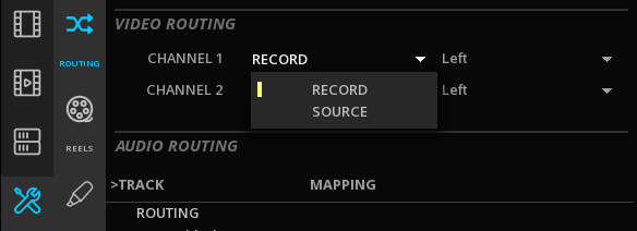
→ For each video channel output capability, you can choose to display either the source viewport or the record viewport.
→ Use the dropdown menu of the last column for managing Stereo 3D content and select which eye to display, with or without Tone Mapping applied.
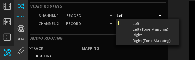
Possible video output mappings:
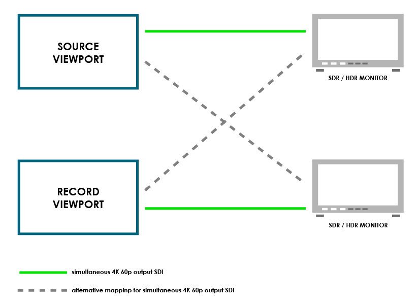
|
Refer to section Video Output capabilities for more information on the supported devices. |

8. TIMELINE
The TimeLine is one of the core features of MIST. Every project made of one or more compositions must go through an editing phase to assemble media, in order to further process it through the color correction tools and the preparation of the deliverables.
In this chapter you will learn the following:
-
Basics for the timeline
-
How to create new compositions
-
How to add clips to the compositions
-
How to load and save compositions
-
How to use the Event Viewer
8.1. Definitions
Below you will have an overview of the vocabulary frequently used in the Timeline section :
| Project |
A project is a structure that is made of several compositions. |
| Composition |
A composition is a structure made of different sorts of media assets: video, audio and timed text (e.g. close captions or subtitles). The metadata associated to the assets are also part of the composition. |
| Layer |
A layer is a placeholder for tracks. The number of tracks depends on the layer category, audio, video or other. |
| Audio Layer |
An audio layer is made of one or several tracks, depending on the audio configuration. The audio configuration specifies the number of audible tracks, usually assigned to individual speakers in a spatial configuration. The following soundfields among others are supported: Mono, Stereo, 5.1, 6.1, 7.1. |
| Track |
A track is a placeholder for segments. Segments can be moved within the track, trimmed, slid (Slide operation) or slipped (Slip operation). |
| Segment |
A segment is a basic unit of editing. It defines the start and end of a media source (audio, video or subtitles) in time. Transitions (video or audio) are special segments that do not represent any media source but rather blend two other segments (audio and audio or video and video). |
8.2. Timeline Basics
The Timeline itself is composed of several parts:
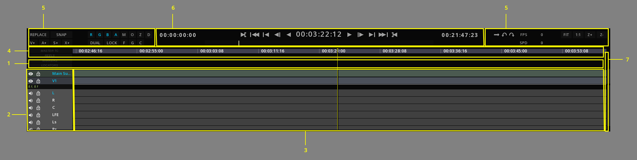
1 |
TimeLine Background |
2 |
Layers Control Box |
3 |
Layers |
4 |
Composition Timescale |
5 |
TimeLine Controls |
6 |
Transport Controls |
7 |
Slider |
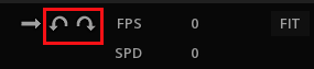
8.2.1. TimeLine Controls
Some controls for the timeline are directly accessible from the GUI (in addition to keyboard shortcuts).
8.2.2. Navigating the Timeline
Depending on the length of the composition, you may need to navigate through the composition back and forth, or change the display scale to reveal more or less of it.
Moving around in the Timeline
To move around the timeline without changing the PlayHead position, is done by using the keyboard and mouse. The following procedure explains how to move the timeline to the left or to the right to reveal the parts that could not be displayed on screen:
→ Press Alt on the keyboard and using the mouse, click the left button and drag the mouse while keeping the left button pressed.
The timeline will be shifted to the left or to the right, revealing the hidden regions.
Zooming the Timeline
You can display the complete timeline or a detailed part of it without changing PlayHead position by zooming in or out the timeline:
→ To zoom IN our OUT use the hotkeys Ctrl++ / Ctrl+-.
→ Alternatively press the buttons Z+ and Z-.

You can also automatically fit the composition in the timeline:
→ To fit the composition in the timeline, use Ctrl+Shift+F or press the FIT button.
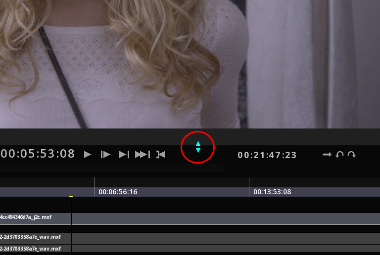
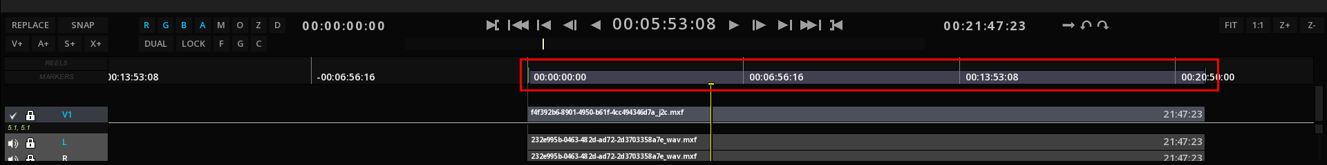
Using the PlayHead
This vertical yellow line indicates where in the timescale the current frame is located. It is also referred as “TimeMarker”.
→ To center the PlayHead in the TimeLine, use the Ctrl+Shift+C.
→ To highlight interesting times (cuts, markers, locators, etc), scrub the PlayHead back and forth with the Snap mode activated: the PlayHead will stop arriving at any interesting time of any track. Scrubbing full speed in Snap mode does not make the PlayHead to stop.
→ To navigate through interesting times ONLY, click Ctrl while scrubbing the PlayHead.
→ To slow down scrubbing capabilities, in order to navigate more easily when there is a lot of interesting times near the PlayHead, click Alt while scrubbing. This will force the PlayHead to move twice slower than normal and allow a better positioning.
TimeLine Navigation Shortcuts
To navigate more easily in the timeline some PlayHead shortcuts are available and detailed in the appendix Shortcuts.
8.2.3. TimeLine Configuration
The TimeLine can be configured to serve your needs depending on the projects you are working on. Possible configurations include:
-
Changing the Timebase
-
Modifying the Layers appearance and manipulating them
-
Manage Layers and create new ones
Changing the Timebase display
The Timebase (or timescale) is by default in timecode mode.
It can be modified to display other time codes or frame information.
The Timeline can be displayed in the following modes:
Normal time Code
Feet + Frame
Frame Number
→ You can toggle the Timebase displays using Alt+T.
Timebase display in Time Code:

Timebase display in Feet + Frame:

Timebase display in Frame Number:

Modifying Layers appearance
The layer appearance can be modified to better display the tracks information if needed.
The TimeLine part can be expanded to display more layers:
→ To expand or collapse TimeLine, place the cursor on the top of the time line until it changes appearance and lift up or down.
→ To navigate in the different layers, use the Scroll Bar on the right of the Timeline.
→ To select several layers, press Ctrl + click and pick the desired layers.
→ To select all the layers, press Ctrl+A.
→ To deselect all the layers, press Ctrl+D.
In the user interface the tracks are separated by a "split". It can be moved up and down to reveal more or less of one of the stacks.
This action reveals additional information like the image resolution for the video layer, or the audio channel number for an audio layer.
-
To resize all the layers altogether, select the layers on the Control Box on the left of the TimeLine using Ctrl + click, keep Ctrl pressed and scroll up or down the mouse reel.
Managing Layers
Some managing operations are available for each type of layer.
→ To display the drop down menu for the layers, position the mouse on the Layers Control Box, select the Layer you want to modify and press right-click.
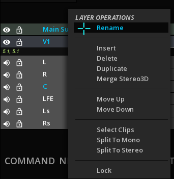
| Rename |
Allows to rename the layer. |
| Insert |
Insert a layer right above. |
| Merge Stereo 3D |
Allows to merge left and right eyes in one track. |
| Delete |
Delete the current layer. Deleting a track removes all clip instances on the track but does not affect source clips available in the library. |
| Lock |
Lock the current layer. |
| Move Up/Down |
Allows to reorder your tracks by moving them up or down. |
| Select Clips |
Selects all the clips in the track chosen. |
| Split |
You can split your audio configuration to mono or stereo tracks |
Layers Manipulation
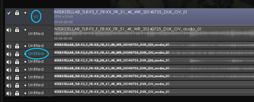
An important notion when manipulating the Timeline layers is the “Active” layer. This is especially important when editing the clips.
Active layers are labelled in blue:
In order to quickly manipulate the layers, you can use the Timeline Hot Box.
→ Place the mouse cursor on the TimeLine background and press Ctrl + right-click to display the Hot Box for the TimeLine ans select LAYER:

The Hot box provides you with short cuts to select or deselect the different type of layers.
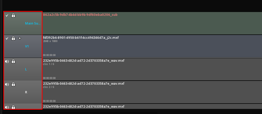
The Layer Control Box also displays important icons:
|
Indicates that the layer is enabled. To change layer status to disabled, click on the icon. |
|
Indicates that the layer is disabled. To change layer status to enabled, click on the icon. |
|
Shortcut to lock the layer. Icon turns red when activated. |


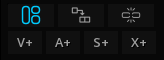
Create new Layers
At any time you can add additional layers to the composition. Layers can be added according to their type, video, audio, etc..
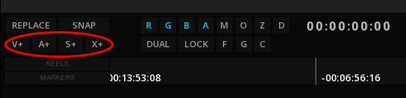
| V+ |
Insert a Video layer on top of all others |
| A+ |
Add an audio layer at the bottom of all others |
| S+ |
Add a timed text layer (for subtitles or closed captioning) on top of the video layers. |
| X+ |
Add an auxiliary track at the bottom of the audio layers. Auxiliary tracks are used to display special metadata tracks like Dolby Atmos, DBox, etc… |
About Auxiliary Tracks
→ Click X+, to display a drop-down menu and chose the appropriate auxiliary track:
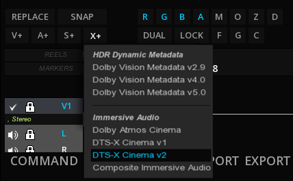
HDR Dynamic Metadata
| Dolby Vision Metadata v2.9 |
use this type for adding a Dolby Vision 2.9 Metadata ISXD track |
| Dolby Vision Metadata v4.0 |
use this type for adding a Dolby Vision 4.0 Metadata ISXD track |
| Dolby Vision Metadata v5.0 |
use this type for adding a Dolby Vision 5.0 Metadata ISXD track |
Immersive Audio
| Dolby Atmos Cinema |
use this type for adding an Atmos track for a DCP package (see DCP with Dolby Atmos) |
| DTS-X Cinema v1/v2 |
use one of these types for adding a DTS-X Cinema immersive audio track for a DCP package. (see DCP with DTS-x) |
| Composite Immersive Audio |
use this type for adding an immersive audio metadata like Dolby Atmos as IAB track for an IMF package. |
8.3. Compositions
Assembling a program from multiple clips is done in a composition. By default every project has a default composition, called “Temporary”. However in a real world project, it is necessary to create multiple compositions for various needs, such as various edits of the same program, etc.
A composition is a structure made of different sorts of media assets: video, audio and timed text (e.g. close captions or subtitles). The metadata associated to the assets are also part of the composition.
It is also definite by a format (width, height, bitdepth, frame rate, sample rate, etc) and a duration.
In addition other composition properties exist such as a marking zone, markers, PlayHeads, etc to help the editing process. Each sort of media is organized into layers: the video layers (located in the video layer stack) and the audio layers (located in the audio layer stack).
Editing of video layers and audio layers can be done separately or jointly.
Layers are composited together in their category (video layers together, audio layers together).
The result of a composition is a video stream and one or more audio streams (one for mono, two for stereo, etc). The rendering of a composition generates a new clip.
In this section, you will learned the following:
-
Adjusting a composition’s duration
-
Managing (Saving, loading) compositions
-
The Composition settings
8.3.1. Composition duration
Composition duration is displayed in dark green over the timescale:
By default, the composition is set on 24h.
The duration of the composition can be adjusted by a simple move (click and drag) of the small handles at each end of the composition’s line.
→ To auto adjust the composition duration to the clips on the timeline, press Alt+Ctrl+F.
The Composition can also be manually adjusted by typing values for the beginning and the end of the composition:
→ Click in the Composition Start and / or End in the Shuttle Bar, and type desired values.

The composition is automatically updated with the new duration.
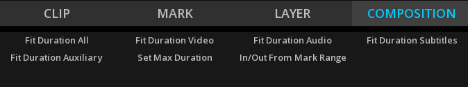
In order to quickly fit the composition, you can also use the Timeline Hot Box:
→ Press Ctrl + right-click on the Timeline itself to display the TimeLine Hot Box and select COMPOSITION. The Hotbox provides you with short cuts to fit the different type of layers of the composition.
|
The duration of the composition affects the playback: if part of a media is outside the composition, it will not be played. |
8.3.2. Composition Management
A project can contain an unlimited number of compositions, each of them with a different output format, frame rate or image resolution.
Compositions are reflecting the content of a Timeline.
To manage a composition, from the Command Panel / Compositions, select one and use right-click to display the drop-down menu:
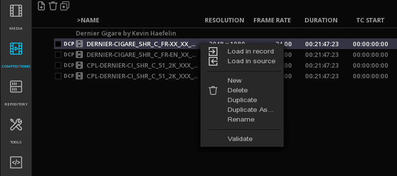
| Load in Record |
Load this Composition in the Record Viewport |
| Load in Source |
Load this Composition in the Source Viewport |
| New |
Create a new composition, with an empty timeline. By default it’s named "NewComposition" |
| Delete |
Delete a composition. This action only deletes a Composition from within the software project and has not effect on a phyical content’s CPL. |
| Duplicate |
Duplicate the entire composition in a new one. Assets and Settings are all duplicated. The new composition has the same name with "copy" at the end. |
| Duplicate as… |
Quick Composition conversion |
| Rename |
Allows to rename a Composition. Enter the name in the field and validate using Enter. |
| Validate |
Opens the Master Validation panel if a Compliance Test Plan is available for this master. |
| Photon |
Only visible in the case of an IMF composition. Opens the Photon validation panel. |
|
When you load a composition, the clips may appear in red for a short time, the time needed to renew the links. In general, except for a graphical subtitle track (e.g. PNG files), the names of the clips are red when there is no associated media: 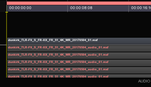
|
Save a composition
The compositions are automatically saved when you leave the project.
→ to manually save a composition, use Ctrl+S.
Convert / Duplicate a Composition
It is possible to quickly convert a composition with another resolution and frame rate.
→ Right-click on the desired composition and chose Duplicate as… from the drop down menu:
→ Create your custom composition format or use the Format drop-down menu to choose a composition preset:
→ To simply copy the composition in a new timeline, use Duplicate from the drop down menu.
8.3.3. Composition Settings
Access the Composition Settings
Composition Settings are accessible from the Command Panel:
In the Composition settings, you will find different kind of settings, presented in tabs:
| GENERAL |
defines the name, the type and the mode of your composition. |
| FORMAT |
defines the way the media is outputted |
| CMS |
Color Management System. This parameter sets the composition either in the native color space of the video clips on the timeline, or switch the composition in ACES color space. |
| DISPLAYS |
defines mastering display and Target Displays. |
| OVERLAYS |
defines blanking information and image burn-ins |
|
All the parameters of this panel will only apply to the current Composition. Loading a new empty TimeLine will restore default project settings. |
General settings
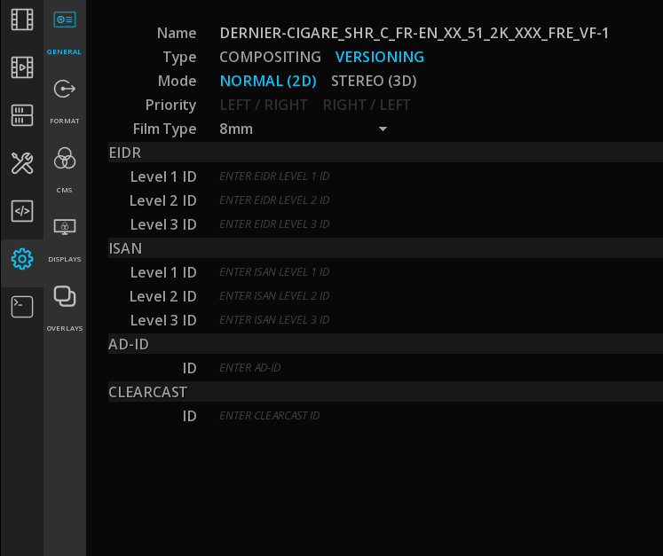
| Name |
Name of the composition. Edit it with a click on the text field. |
| Type |
Choose the type of your composition: COMPOSITING or VERSIONING. |

| Mode |
This parameter set the composition in 3D STEREO or in normal 2D mode. In 3D STEREO mode, you can also chose the priority of the left and right eyes. More information about 3D mode is available in the 3D STEREO guide. |
| Priority |
Enabled when in 3D Stereo mode. |
| Film Type |
Setting a Film type will define how the TimeLine is calculated in Feet+Frames (see section TimeLine in the Player chapter). |
| EIDR and ISAN levels |
Enter EIDR and ISAN identifyers here. The 3 different levels ID are supported. |
| Ad-ID & Clearcast |
Enter Ad-ID identifier and Clearcast number here. |
|
EIDR, ISAN, Ad-ID and Clearcast information entered here will be embedded in the content’s metadata. |
Format
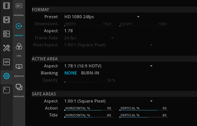
| Format Preset |
Select the desired output preset in the drop down list: |
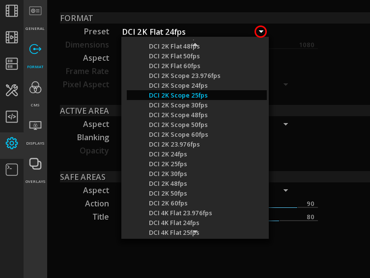
|
When chosing a different image resolution, in order to fit the picture in the expected output canvas and therefore avoid any undesired crop, use the Pan and Scan function. |
| Format Custom |
Choosing Custom in the preset list allows you to manually set the output: |
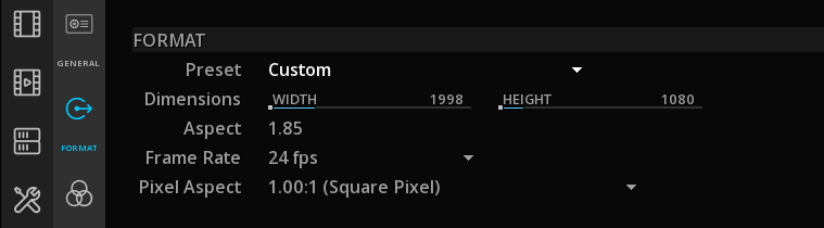
- Dimensions
-
Use the slider or click on the digits to edit the text and enter the desired value.
- Aspect
-
The aspect ratio of the canvas is automatically calculated based on the dimensions.
- Frame rate
-
Choose if the composition will be played from 14 up to 72 frames per second. this setting will affect the playback speed. For more information refer to the TimeCode section of this manual.
- Pixel Aspect
-
For anamorphic content: select the desired aspect ratio of the pixel.
| Active Area Aspect |
select the active image area ratio from the drop down menu thus to exclude letter and pillar boxing from any processing or analysis.
|
| Blanking |
Burn in blankings (letterhead and pillar boxing). Blankings are not affected by color or contrast corrections. |
| Opacity |
Choose more or less opacity for the blankings: double-clik on the value to edit it or use the slider. |
| Safe Area Aspect |
Select the safe area aspect to display. |
| Safe Action and Title |
Define the percentage of tolerance for safe action and safe title in relation with the chosen safe area aspect. Double-clik on the value to edit it or use the slider. |
→ Press Alt+F to display Safe frame on the Viewport.
CMS

This tab is dedicated to the choice of a Color Management System for your current composition. For more information, please read carefully the Color Management System chapter.
Displays
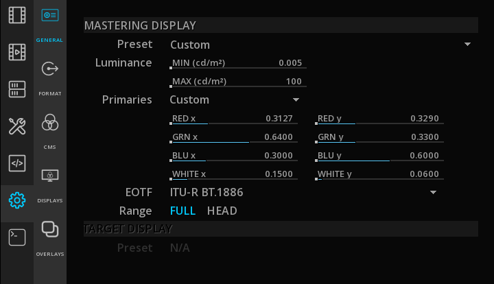
The Display tab allows you to define a Mastering Display or a Target Display for your content.
This is also the place to manage the display’s LUTs.
For more informations, please read carefully the Mastering Display chapter.
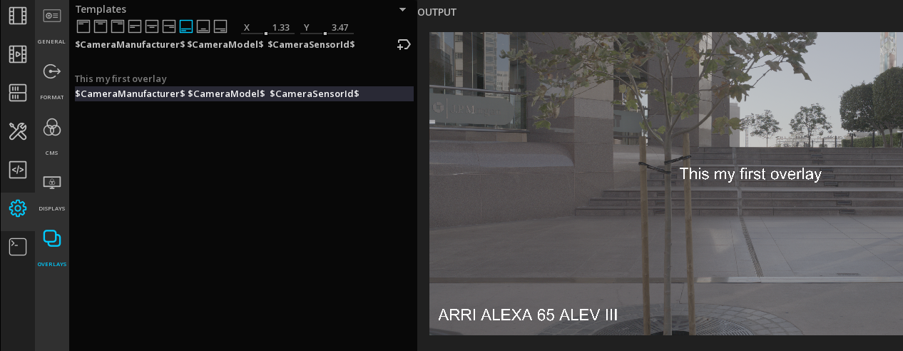
Overlays
You can use Overlays to burn some metadata on the image Timecode, file name, and camera metadata.
Overlays work using text and metadata that you can modify to create burn-ins with a variety of styles.
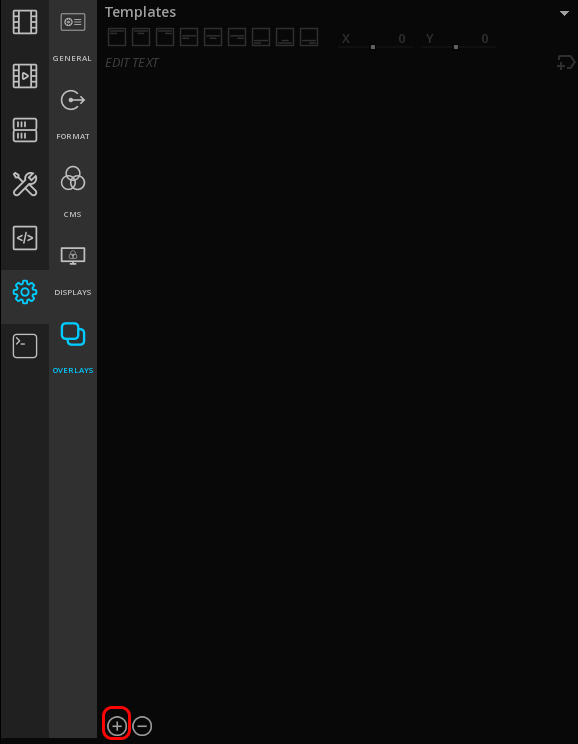
Add a custom text Overlay
→ Click on + to add a new overlay. By default the tag "text" appears on the list.
→ Select the overlay on the list to edit it:
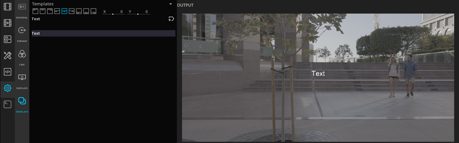
→ To modify the text, click in the editing text field:

and validate with enter.
You can style the text using the Rich Text Markup specification.
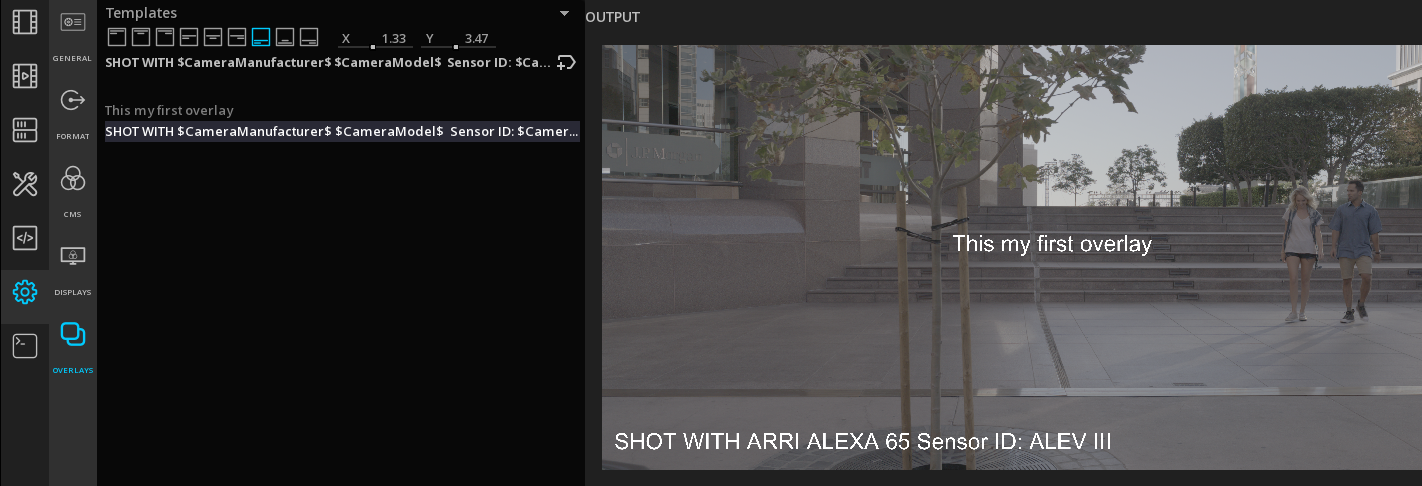
Add a Metadata Overlay
Some important metadata are directly available using metadata tags.
→ To add one, select the overlay in the list and click on +tag icon:

and select a metadata in the drop-down menu:
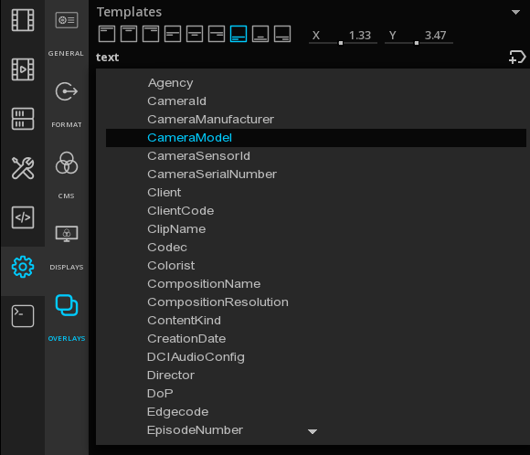
You can add several metadata tags for each overlay:
and mix custom text with metadata:
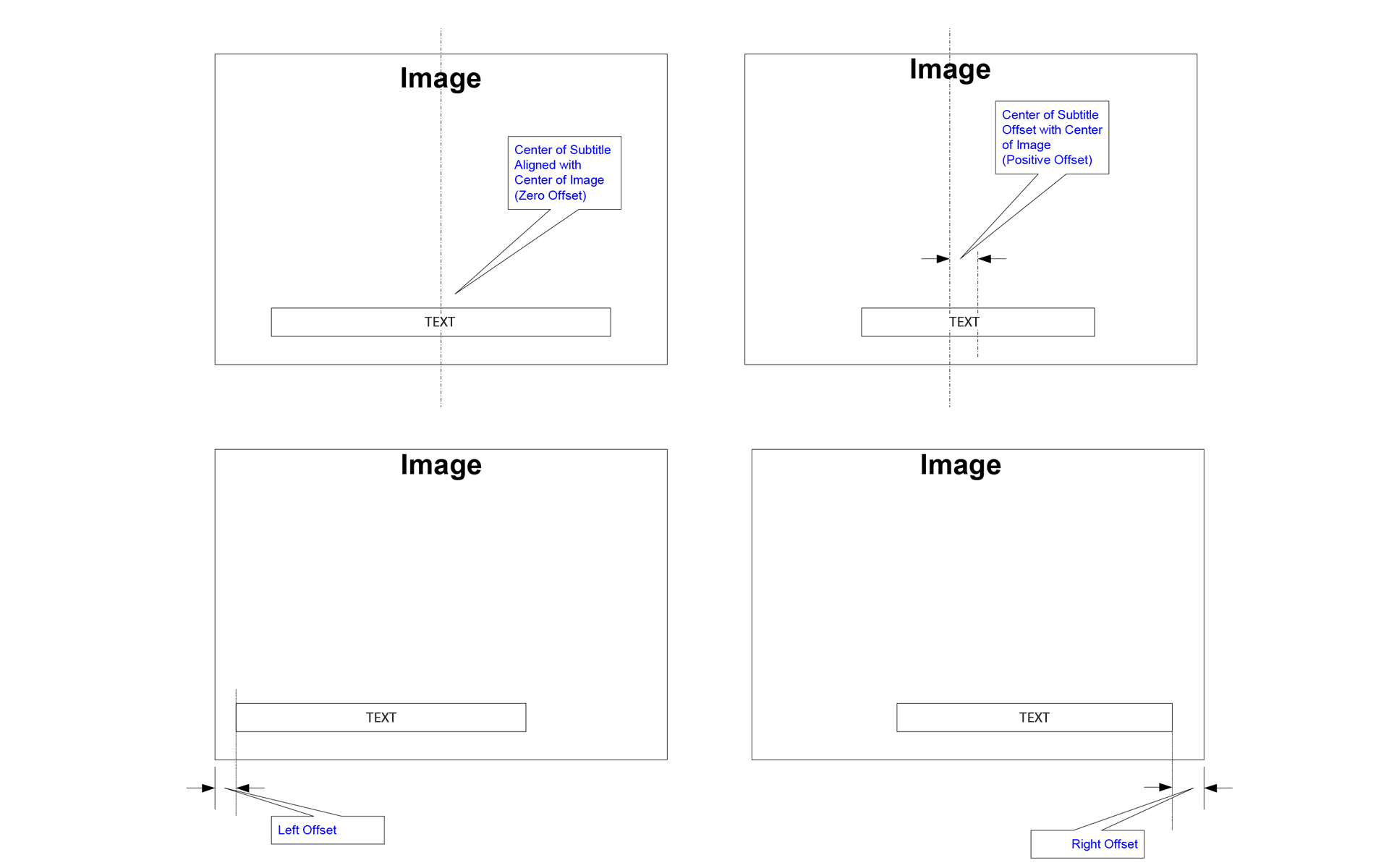
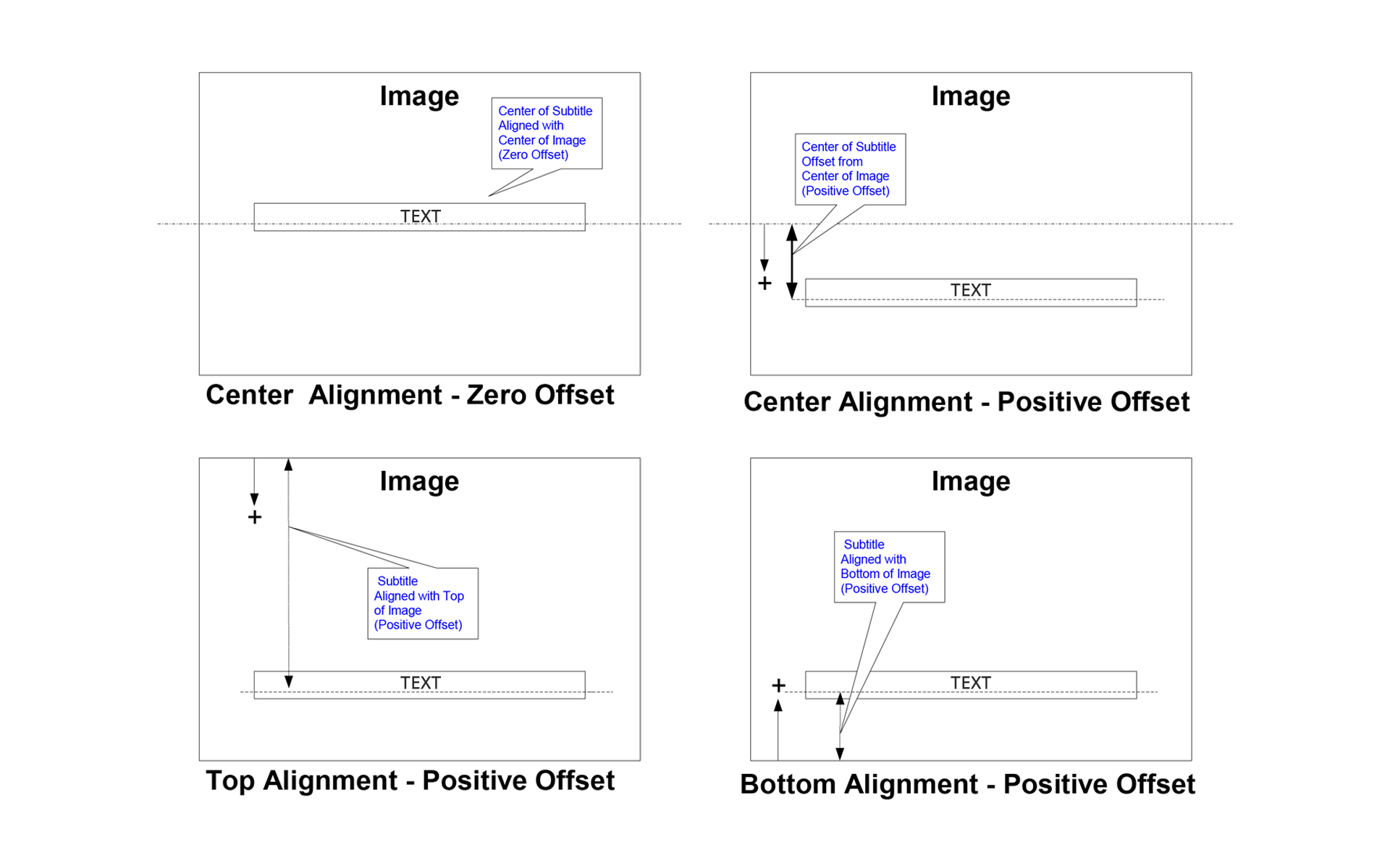
Modifying overlay positioning
The positioning of overlays in the image are defined by offsets to vertical and horizontal positioning.
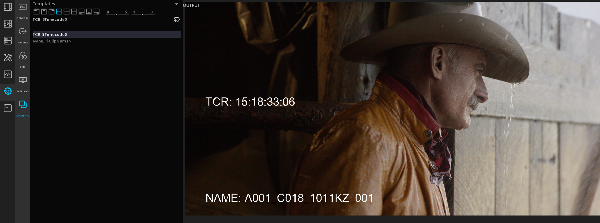
→ Use the text alignment icons and the X and Y axis to position the overlays at the desired place.
Text Horizontal positioning:
Text Vertical positioning:
Saving Overlay templates
→ To save overlays settings as a template, click EXPORT on the timeline menu and select in File Type "Marquise Technologies Overlays Template":
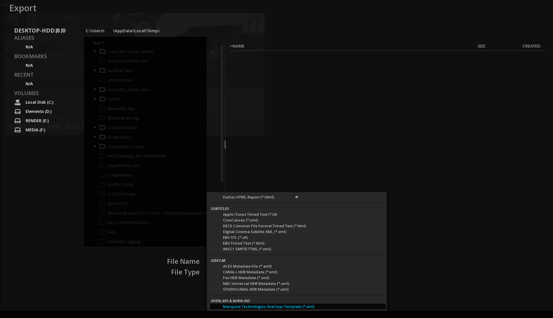
→ Select a location to save the template (by default it will be saved in the temporary folder of the User).
→ To upload a saved Overlay template, click IMPORT on the timeline menu and browse the file system. You can use the File Type info to narrow the search.
|
To display an Overlays Template in the Overlays Template drop-down menu, it must be saved in the Software installation directory folder C:\Program Files\Marquise Technologies\$software_version$\resources\templates\overlays :
|
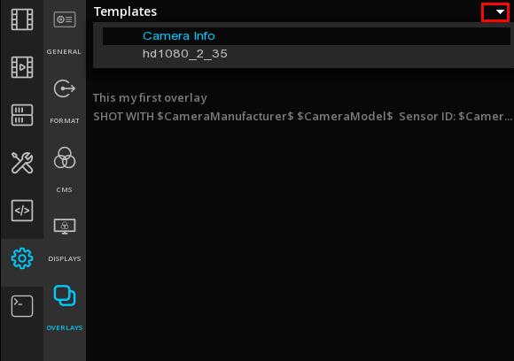
→ Click on Templates to open the drop down-menu and select a template:
A list of overlays for this template is displayed.
→ Click on the desired overlay to modify it.
8.4. Markers
Markers define regions of a composition that have a specific meaning.
Typical information located by Markers are for example First frame of Credit, or Commercial break.
→ To access the Markers panel, click on TOOLS in the Command Panel:
8.4.1. Adding markers
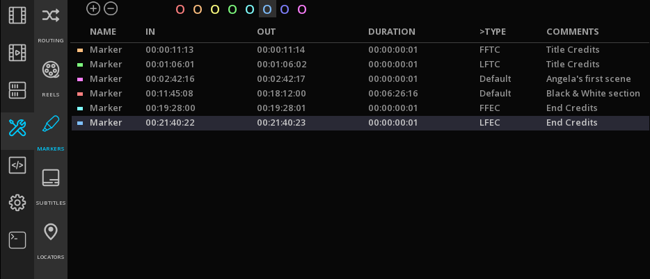
→ To Add a Marker, position the Playhead on the desired timecode and in the Markers panel select a color and click +. The Marker is set for a default duration of 1 sec.
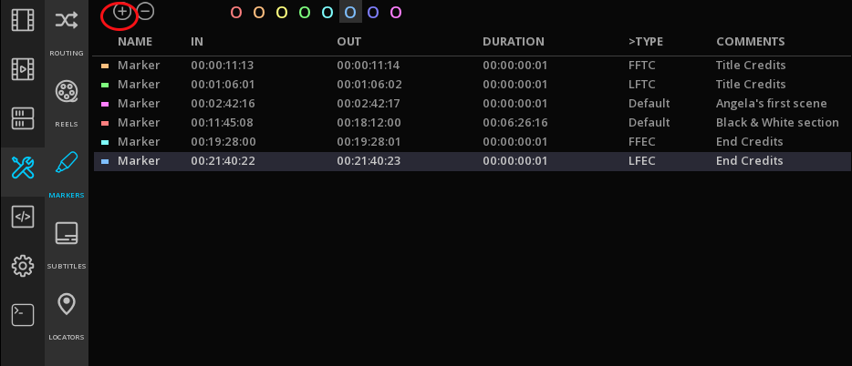
→ To mark a range, first define your range and in the Market panel click +.
→ To delete a Marker, select it in the Markers' list and click -.
Markers are represented in the TimeLine by colored triangles and positioned in the Marker’s track:

8.4.2. Navigating through Markers
You can navigate from Marker to Marker using different options:
→ Double click on a time code in the Markers list for the PlayHead to jump directly to the related frame in the TimeLine.
→ Use shortcuts Shift+U for Next Marker and Alt+U for Previous Marker
Additionally, when the PlayHead is positioned on a particular Marker, it is highlighted in the Marker’s list.
8.4.3. Editing a marker
SMPTE markers labels are supported. To add some, select the desired Marker in the list and click on Default on the Type column.
This action display the Markers drop down menu.
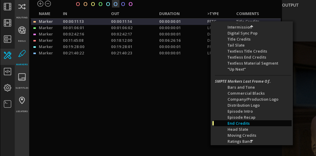
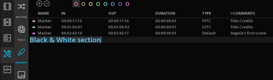
You can also add custom comments.
Select the desired Marker in the list and click on Default on the Comments column and add your custom text:
8.4.4. Moving Markers
You can move or change the duration of a marker directly in the timeline:
→ Position the mouse on the IN or OUT point of the marker until the cursor shows  and move the marker to the new position.
8.4.5. Exporting / Importing Markers
Save Markers
It is possible to export the markers information in XML:
→ Click on EXPORT at the bottom of the TimeLine and choose Markers in the File Type drop-down menu:

→ Choose a location for your file and enter a name.
→ Validate with OK.
Import Markers
→ To import a Markers file, click on the IMPORT at the bottom of the TimeLine and choose Markers in the File Type drop-down menu.
→ Browse the folder tree on your left, select the file and click OK.
|
Only Markers created using ICE or MIST can be loaded. If you want to import an external file, you can use the Locators. |
8.5. Locators
If they are similar to the Markers, Locators are only used for custom comments.
→ To access the Locators panel, click TOOLS in the Command Panel:
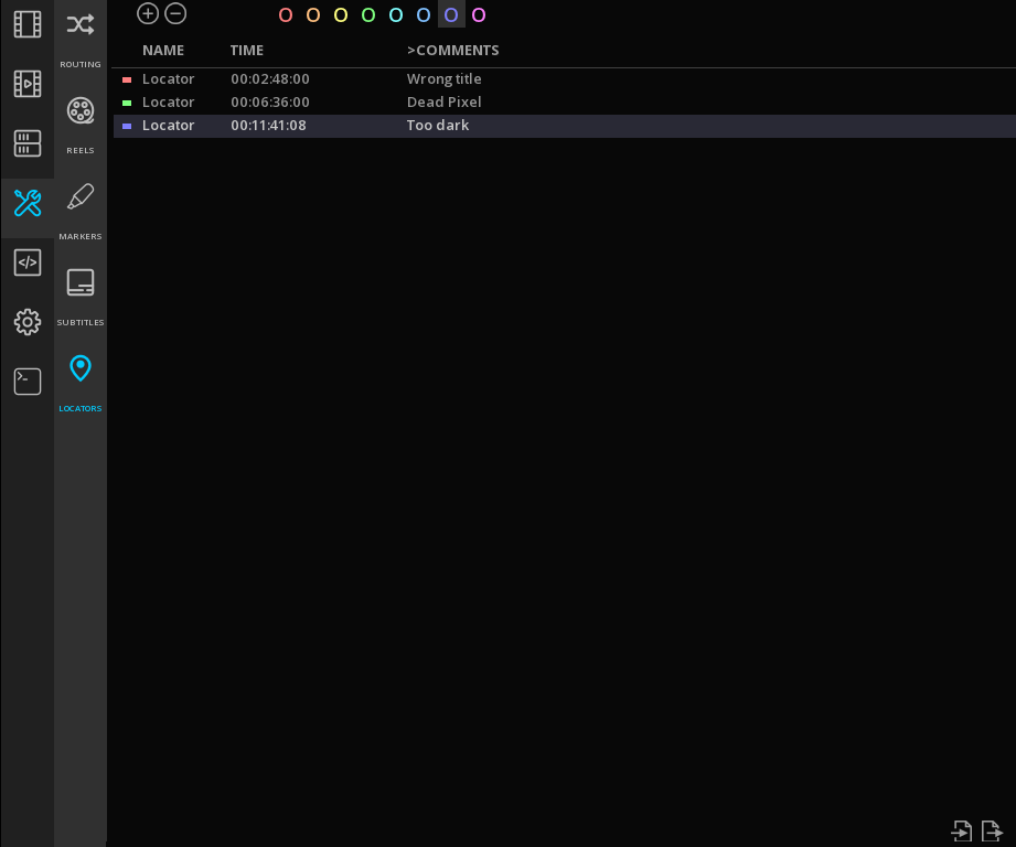
Locators are represented in the TimeLine by colored squares ans positioned on the Locators' track:

8.5.1. Adding Locators
→ To Add a Locator, position the Playhead on the desired timecode and in the Locators panel select a color and click +.
→ To delete a Locator, select it in the Locators' list and click -.
|
You can create several Locators at the same timecode, however on the TimeLine only the last Locator entered will be displayed. |
8.5.2. Navigating through Locators
You can navigate from Locator to Locator using different options:
→ Double click on a time code in the Locators list for the PlayHead to jump directly to the related frame in the TimeLine.
→ Use shortcuts P for Next Locator and Alt+P for Previous Locator
Additionally, when the PlayHead is positioned on a particular Marker, it is highlighted in the Marker’s list.
8.5.3. Editing a Locator
→ Select the desired Locator in the list and click on the empty field in the Comments column and add your custom text.

→ To rename a Locator, double click on its name and enter the new text.
8.5.4. Moving Markers
You can move a Locator directly in the timeline:
→ Position the mouse on the locator until the cursor shows and move the locator to the new position.
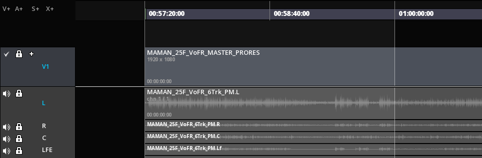
8.6. Reels
The Reels tool allows to define which zones of the timeline are to be exported as reels or chapters in your newly created deliverable.
Each Reel has an in point and an out point. If you simply export a file without indicating any reel in the timeline then MIST uses the composition start and end points to define the duration of the default reel of the file.
|
Once you have defined a reel in the timeline it has priority over the composition start and end points and becomes the new duration of the exported deliverable in place of the composition start and end points. |
Each additional Reel placed in the timeline adds a new segment of picture sound and subtitles to the overall content of the exported file.
Each new reel is automatically incremented at its creation with a reel number; 1, 2, 3, etc. The reel numbers define the order in which the reels will appear in the in the file so it is important to create reels in the correct playback order when mastering your new deliverable. You may place as many Reels into the MIST timeline as you wish as well as delete them.
As described above, the portions of the picture, audio and subtitle clips that are within a reel’s in and out points will be included in the final export.
Any portions of clips that are outside of a reel will not be exported at all. This means that the picture, audio and subtitle essences are processed as independent blocks for each reel.
8.6.1. Creating Reels
-
Before creating a reel, define a range into the timeline with the In and Out mark by pressing I and O keys. The selected region will appear highlighted as shown below:
-
In the Command Panel, choose TOOLS / REELS
-
Choose a label color by clicking on the desired color and click + to create the reel. Rename it if needed by double-click on its name.

Once created, duration as well as the IN and OUT points of reels cannot be changed. In order to do it, a new reel has to be done. To create all the desired reels, repeat the process as many times as necessary. The reels are listed in order of timecode and not by their order of creation.
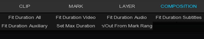
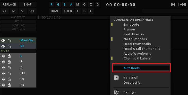
8.6.2. The Auto Reels function
The Auto Reel function is a very useful tool creating automatically the reels.
Right-click on the TimeLine background to access the COMPOSITION OPERATIONS drop-down menu and choose Auto Reels:
A window appears in order to choose the desired method and settings:
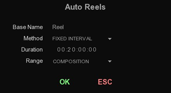
| Base Name |
You can modify the title of the reels (same for all of them). |
| Method |
Select the auto-reel method: |
| Range |
Choose the apply the auto-reel on the Composition, on the Marked range or the Actual total of the clips on the timeline. |
All of these method can be applied by choosing different range such as:
Composition, Actual Total or Marked In/Out.
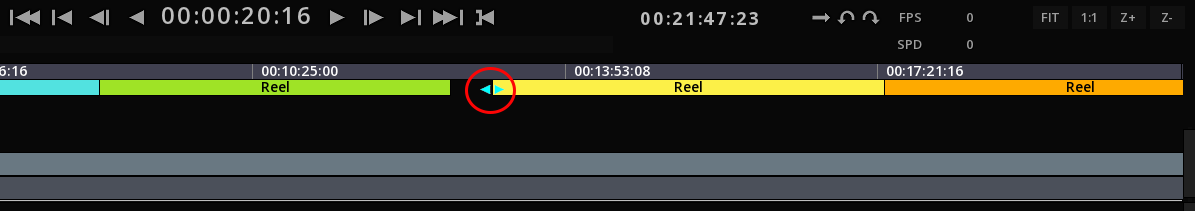
8.6.3. Editing Reels
-
to rename a reel, double click on its defaults name to display the text field editor.
-
to add a comment for a reel, double click on the empty field in the column COMMENTS.
-
To move IN or OUT point for a Reel, position the mouse cursor at the desired IN or OUT point of the Reel and slide horizontaly:
reel-move.png
8.6.4. Deleting Reels
In order to delete a reel, click on the desired reel and click - to validate the deletion of the selected reel.
|
this action cannot be undone. |
8.6.5. Navigating from Reel to Reel
You can navigate from Reel to Reel using different options:
-
Double click on a time code in the Reels' list for the PlayHead to jump directly to the fist frame of the reel in the TimeLine.
-
Use shortcuts Alt+Ctrl+Page Up| for Next Reel and Alt+Ctrl+Page Down| for Previous Reel
Additionally, when the PlayHead is positioned on a particular Reel, it is highlighted in the Reels' list.
8.7. Playback
8.7.1. Playback Modes
There is several modes for playback available:
|
Play Once |
Play the current composition just once |
|
Play ping pong |
Play backward then forward the composition, endless. |
|
Play Loop |
Play back the current composition, endless |


The “Play once” mode is set by default.
→ To toggle to the other modes, click on the icon until the desired mode is displayed.

8.7.2. Playing Back a Marked Region
To play a specific region of the composition, mark the desired range with IN and/or OUT points:
| IN point | OUT point | Description | Shortkey |
|---|---|---|---|
SET |
SET |
Play forward in the marked region |
Alt+Space |
SET |
SET |
Play backward in the marked region |
Alt+Ctrl+Space |
SET |
None |
Play forward from the IN point to the end of the compositio |
Alt+Space |
SET |
None |
Play backward from the end of the composition to the IN point |
Alt+Ctrl+Space |
none |
SET |
Play forward from the beginning of the composition to the OUT point |
Alt+Space |
none |
SET |
Play backward from the OUT point to the beginning of the composition |
Alt+Ctrl+Space |
|
If the PlayHead is inside the marked range, the playback starts at the PlayHead origin |
8.7.3. Playback Information
The timeline’s interface displays some playback information such as:
| FPS |
Current frame rate of the playback in frames per second. |
| Speed |
Define the increment between the frames: |
→ Use JKL controls to modify the playback speed.
8.8. Event Viewer
8.8.1. Overview
One of the major differences between a colorist and an editor is the fact that they have different requirements regarding the display of the shots and how to navigate from one to the other. While the editor will be mostly using the timeline to navigate in the composition, a colorist is more likely to prefer another method. The reason for this is quite simple : when color grading a show, the focus is on the shots as individual pieces of content and their placement in the chronology of the show or the possible transitions between them is not relevant.
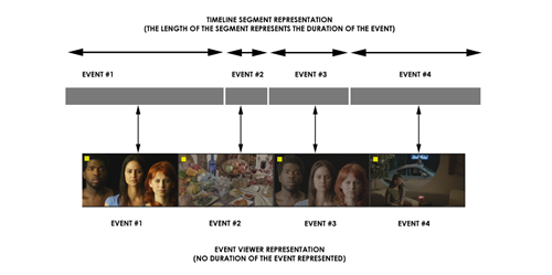
A classic editing timeline is far from sufficient to serve the purpose. Instead another navigation tool is preferred. This navigation tool is the Event Viewer (sometimes called the shot viewer).
The Event Viewer also displays the clips available on the timeline in a chronological manner; however, it represents each clip with a preview of one of the frames of the clip. Each preview is displayed next to each other and their dimension is always the same. As a matter of fact, the Event Viewer does not visually represent the length of a clip (or shot). Again this information is of little interest during the color correction process. The diagram below shows you the difference between the timeline and the Event Viewer representations :
Besides the visual difference, there is also the fact that an Event Viewer allows only a limited number of editing operations. These editing operations are the common ones used by a colorist or an assistant and once again they only serve the purpose of permitting operations needed in this context.
It is also worth noting that the name (i.e. Event Viewer) refers to the objects it displays as “events” and not clips or shots or anything else. From the colorists point of view the timeline is an assemblage of pieces of material that have been spliced together in a chronological manner.
Each of these objects are called “events” because they are actually events occurring at a certain time during the playback of the final show. Once an event is over, it is immediately followed by another event (which can be another piece of material, a transition, or simply a black screen).
A colorist will work on each of these events and make sure that they are all consistent from the color point of view and correspond to the intentions of the director of photography.
In addition to the navigation shortcuts offered by the Event Viewer, there is another important reason to use it. The Event Viewer also gives you access to multiple grading versions per event.
In this chapter, you will learn the following things:
-
How to show and hide the Event Viewer.
-
Understand the information displayed in the Event Viewer.
-
Navigate through events.
-
Insert, delete and replace events.
-
Store and recall various color correction versions per event.
8.8.2. Accessing the Event Viewer
The Event Viewer is a key element during a grading session. As a matter of fact, colorists use it much more than the regular timeline. Therefore it must be accessible at any time by using all the connected input devices, i.e. the mouse or the stylus, the keyboard and of course the control surface.
Using the mouse
If you use the mouse or the stylus, then the Event Viewer can be accessed by clicking on EVENTS located on the lower right side of the screen.
Once you have clicked on EVENTS, its color will change to light blue to indicate that the Event Viewer is being displayed. Clicking once more on EVENTS will cause the Event Viewer to be hidden again.
Using the keyboard
When using the keyboard to show or hide the Event Viewer, you must use the E key shortcut. By pressing E once, you will force the Event Viewer to be displayed. Pressing E again you will force it to be hidden again.
Using the control surface
Accessing the Event Viewer with the control surface is done via a dedicated key. Usually the same key is used to toggle the presence on screen of the viewer. Please refer to documentation for your control surface provided with the software for more information on how to access the Event Viewer.
Once you have used one of the methods above to reveal the event viewer, it will be displayed at the bottom of the screen, like illustrated in the screenshot below:

8.8.3. Understanding the Event Viewer
The Event Viewer always displays the events on the currently active layer only. In a multi-layer composition, you must activate the layer you want to work on first. The Event Viewer is immediately updated with the events (clips or holes) existing on the active layer.
The events are arranged chronologically from the left to the right. The leftmost event is the first event on the timeline, while the rightmost is the last event on the timeline.
The current event (the one that you are working on) is always centered in the display. Towards the left you will find the preceding events (or past events), while to the right you will have the upcoming events (or future events).
The diagram below shows multiple events on the currently selected layers and their organization from left to right:
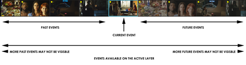
As previously explained, the current event (the one that you are working on) is always centered. To distinguish it from the other surrounding events, it has a light-blue blinking border.
Besides the indication of which event is currently worked on, there are other indications that the current event carries and that are worth looking at. The close-up screenshot below shows the current event centered and exposes some extra information :
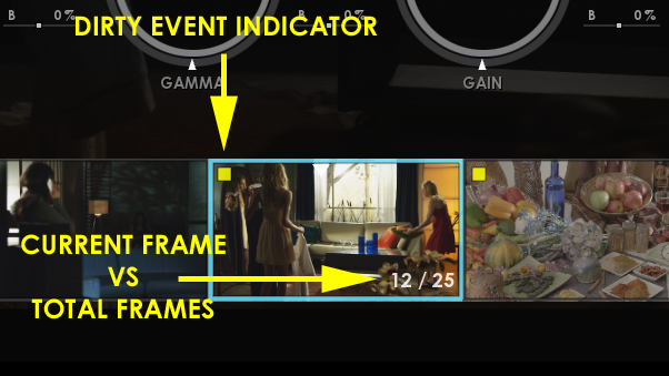
The current event also has a display of the current frame number as well as the total number of frames. This indication is updated as you navigate through the event.
Moreover, each event has a “dirty” flag that is displayed on the top-left corner of the thumbnail. This flag indicates that the event has been modified and the modifications have not been confirmed or saved. So, if you don’t save your composition by yourself, the auto-save could do it and then make the flag disappear.
8.8.4. Navigating through shots
One of the top purposes of the Event Viewer is to provide a fast visually-oriented navigation through the shots available in the currently active layer. Rather than locating a segment in a timeline, the Event Viewer allows you to visually locate the event you want to go to by looking at his thumbnail.
The navigation is performed by either using the mouse and stylus, or the same navigation keyboard shortcuts as in the timeline or eventually by using the transport controls of your control surface. In this section, only the specific Event Viewer navigation methods will be explained.
Using the mouse
The navigation to the neighborhood shots (those actually visible) is done via the mouse or stylus. To quickly go to any of the visible shots, you simply need to double-click on its thumbnail.
The PlayHead will immediately move to the selected event and its first frame will become the current frame. The new event also becomes the current one and it is centered in the Event Viewer. The various information usually displayed on the current event is also updated to reveal the current status.
Select an active track with the Event Viewer
→ Like the timeline in the editing mode, you can move from a track to an other by using the shortcut Ctrl+Page Up / Ctrl+Page Down. If the track is empty, it will show you only one event with “No clips on track !” written.
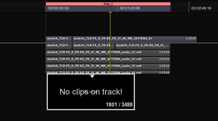
Moving through the Event Viewer
→ As we mentioned before, to move through the Event Viewer, you can use the PlayHead on the timeline like in the editing mode or use the same shortcuts (e.g. press SHIFT + Left to move ten frames before). There is cursor on the top of the current event selected to let you know where you are regarding the duration of the clip.
8.8.5. Inserting shots
During the grading process it could happen that a missing shot needs to be inserted in the timeline. This can happen for various reasons, some being the fact that a VFX shot was missing or you simply need to insert some titles for the purpose of mastering. Whatever the reason, the best way to edit the timeline is still by using the editing tools in the actual timeline or editing mode.
Nevertheless, for some simple operations it is also quite handy to insert shots by placing them between other shots via some quick methods. The event viewer offers the possibility to insert shots before or after a shot, by dropping one or more clips attached to your pointing device.
To insert before or after a shot through the Event Viewer, some conditions need to be met :
-
one or more clips must be attached to the cursor.
-
you must hover around one of the event’s drop zones.
-
Finally you must release the clips by clicking on the drop zone.
Also you have first to decide if you want to insert or replace by clicking on the button on the top left corner of the timeline to toggle from one to another (or you can press the hotkey INSERT). The one showed will be the one used :
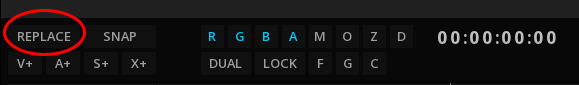
Inserting before the current shot
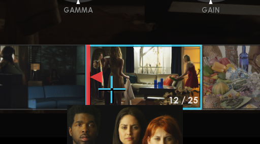
In the screenshot on the left, the mouse cursor is hovering around the leftmost area of the event. A red bar with a left-oriented arrow head appear to indicate that the clip can be inserted before the one you are on.
Inserting after the current shot
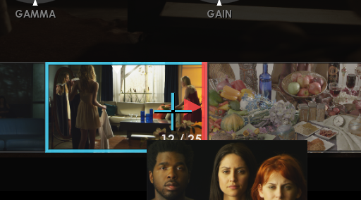
In the screenshot on the left, the situation is similar to the one describe above, but this time the red bar and the arrow head are oriented to the right. This indication means that the clip can be inserted after the one you are on.
Once you have clicked on one of the drop zones described above the clip(s) attached to the cursor will be dropped either right before or right after the event you were hovering around.
8.8.6. Replacing shots
Just as important as being able to insert shots on the fly, without any conforming or editing operations, it often happens that shots simply need to be replaced. There are many ways to replace shots on the timeline and every method has its pros and cons. While the timeline and more editing-oriented and the conforming operations are more adapted to building or adapting full compositions to media changes, they still are somehow complex operations.
A simple method is provided by the Event Viewer, facilitating shot replacement without the need to understand editing or conforming.
To replace one or more shots through the Event Viewer, some conditions need to be met:
-
one or more clips must be attached to the cursor.
-
you must hover around the center of the event for which you need to replace the media.
-
Finally you must release the clips by keeping the Alt key pressed and clicking on the center of the event.
|
If you have multiple clips attached to the cursor, then the next events will have their media replaced as well, starting with the event you started the operation on and continuing with the next events to the right. The operation is fully terminated when all the clips attached to the cursor are released. |
8.8.7. Selecting shots
During the grading process shots must be selected and deselected to perform various operations on them as a group. Shots can be selected any many places with the exact same effect on them, however the event viewer also allows some basic selection operation for the sake of convenience. Below are listed the selection operations that can be performed directly in the Event Viewer.
Selecting and deselecting individual events
The most used type of selection is to select shots individually, one by one. This operation can be accomplished either by using the mouse or the stylus or the control surface.
Using the mouse
To select individual shots with the mouse or the stylus, you need to hold the Ctrl key pressed and click on the event. When doing so, the event gets a light blue shade to indicate that it is selected.
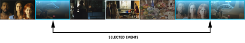
Using the control panel
Individual events can also be selected using the control panel. However, since a control panel does not allow to pick events at random, you position the PlayHead on the event you want to selected and use the dedicated button on your control panel.
Selecting and deselecting all events
Another very used type of selection is when all events are selected or deselected at once. There is no dedicated method for this in the event viewer, so your only option is to use the keyboard as described below.
Using the keyboard
When using the keyboard, you must press Ctrl+A to select all the events. To deselect all the events, you must press Ctrl+D. Depending on the operation, the events with either get all highlighted with light blue or return to their normal state.
|
When selecting or deselecting all the events, the effect is not limited to the events visible in the event viewer. As a matter of fact, all the events in the timeline will be affected. |
9. EDITING
The Non Linear Editing TimeLine of MIST offers numerous editing functionalities for editing the content of a composition.
The selection of clips in the timeline as well as in other parts of the user interface is probably the most common operation when working with the software. Typically more complex operations on clips would need to have one or more clips selected before proceeding.
9.1. Working with Clips
9.1.1. Adding manually clips to a Composition
Once you have dropped your media in the Media tab of the Command Panel (see Media Tab, you can start adding the clips on the Timeline.
There are several ways to add clips to a composition and they all depend on the context. Some methods will be more appropriate than others in some particular cases.
Sequential Paste
This is the easiest method to manually drop some clips in the timeline.
The clips will be placed in the timeline automatically at the playhead position, one after the other, in the order you have selected them in the Media tab.
-
Select the clip in the Media tab of the Commad Panel (clip turns in grey when selected)
-
Using the mouse, click on the thumbnail then lift it with a quick swipe with the left mouse button. This process is called Lift, Carry & Drop.
The Clip will be attached to the mouse:
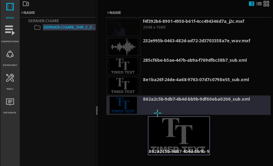
To import several clips, select them in the Media tab in the order you want them on the TimeLine using Ctrl + Left mouse button then click on any thumbnail and lift them with a quick swipe of the left mouse button:
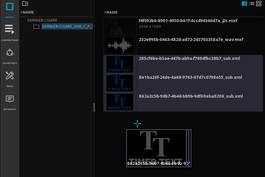
→ Once the clip(s) is/are attached to the mouse, type Ctrl+V to drop the clip(s) on the timeline.
The clips will position themselves on the layers, at the playhead position.
|
The Timeline must be configured with the right number of audio tracks prior to the import. This can be configured either from the Project properties, or by adding manually additional layers (press A+ or S+ for example). |
→ Too keep the clip(s) attached to the mouse for pasting them again, choose the option Keep Clips after Drop in the Project Settings / User Interface. When this option is enabled, press Esc to free the mouse.
Stacked Paste
In Stacked Paste mode, the clips will be placed in the timeline in pile, one below each other, starting from the playhead location.
→ Select the clips in the Media tab as mentioned above
→ Once the clip(s) is/are attached to the mouse, press Ctrl+Alt+V to drop the clip(s) on the timeline.
→ Press Esc to free the mouse.
Extended Pasting
When none of the above methods is convenient, extended paste functions are available.
→ With the clip(s) attached to the mouse, right-click on an empty area of the timeline to display the dropdown menu:
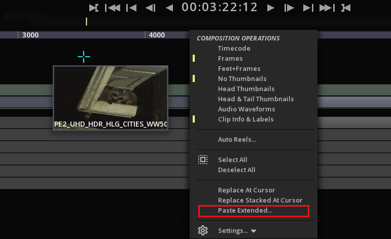
This action opens the Paste Extended tool box:

→ Select the desired paste mode with the drop down menu to be applied either on the current layer or on a new one.
The various paste methods include:
| By Source TC |
will place the clips at specific places in the composition, according to their source timecode. |
| By Increasing Source TC |
will place the clips one after each other but sorted by their source timecode. |
| Alphanumeric order |
will drop the clips one after each other sorted by their name in the increasing alphabetical order. |
| Reverse Alphanumeric order |
will drop the clips one after each other sorted by their name in the reverse alphabetical order. |
Clip and composition frame rate
After the import, if your clip appears in red on the TimeLine, it means that your composition settings have not the same frame rate than your clip:
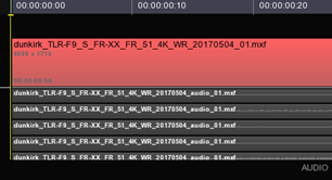
→ To modify them, go to the Composition settings in the Control Panel and change them manually, or
→ Right-click on the clip itself to display the Clip Operations drop down menu :
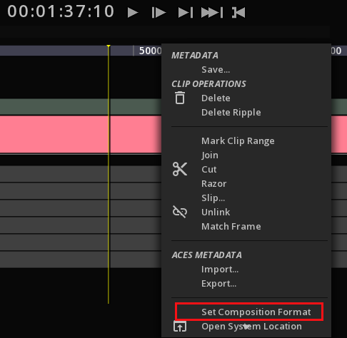
→ Choose Set Composition Format to automatically adapt the composition settings to the clip properties.
9.1.2. Selecting clips
→ To select a clip on the track, click on it. Clip will change color to light grey.
→ To select several clips, use Ctrl + click on each of them.
→ To select all the clips, start to select one clip then use Ctrl+A.
→ To deselect clip(s), use Ctrl+D.
→ To select a range of clips, position the mouse on the track next to a clip you would like to enclose and press Shift + left mouse button and drag the mouse over the desired clips. The covered range is bordered in blue.

Alternatively you can use the TimeLine Hot Box to quickly manipulate the clips:
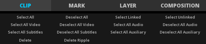
9.1.3. Removing clips
You can remove an entire clip or a range of frames from the composition using several methods :
Delete Ripple
This deleting mode allows to delete a clip without leaving a gap in the Timeline.
→ Select the clip(s), and press Backspace on the keyboard.
Lifting clips or a range of frames
Lifting is the process of removing one or more clips or a range of frames from the composition. The range of the composition to be lifted is defined by the mark in/out range. When lifted, the marked range leaves a gap of the same duration as the mark in/out range.
In order to remove a portion of the composition using the Lift operation, you need first to mark the range using the Mark In/Out tool :
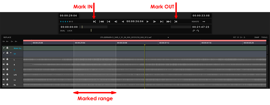
→ to remove a marked region, on the TimeLine background to display the Composition drop-down menu and select Clear Marked Range or Clear Mark :
→ Alternatively you can use the shortcuts Alt+I and Alt+O to set / remove the marked range.
Once the region is marked, to perform the lift you can:
→ press Ctrl+L or
→ display the Composition drop-down menu using right-click on the TimeLine background and select Lift Marked Range.
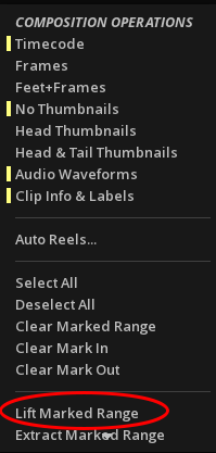
Timeline after a LIFT operation:
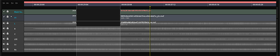
|
This operation occurs on the active layers only. |
Extracting clips or a range of frames
Extracting clips is a process similar to Lift, however there is no gap left by the removed marked range. The remaining clip parts or full clips that were on the right of the mark Out point are moved backwards to the left to fill the gap (also called ripple deletion).
To Extract a clip or a range of frames you must first mark a range and then :
→ press Ctrl+E or
→ display the Composition drop-down menu using right-click on the TimeLine background and select Extract Marked Range.
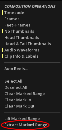
Timeline after an EXTRACT operation:
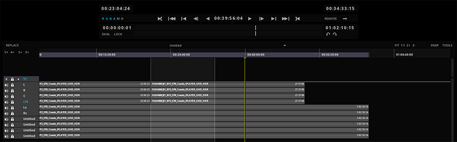
|
This operation occurs on the active layers only. |
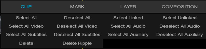
9.2. Cutting clips
You can split a clip in the Timeline by using the razor tool. Splitting a clip creates a new and separate instance of the original clip. It can be useful when you want to use different effects that can’t both be applied to a single clip, such as different color corrections. When you split a clip, MIST creates a new instance of the clip and any clips to which it is linked.
When several clips audio or video are on the timeline, splitting clips will affect all the clips at the time marker or at the razor line that are active or selected.
→ Select the razor tool in the “clip operations” menu (a red line appears) and click a clip in the Timeline where you want to split it.
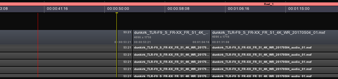
You can use mark in and out to split your clip by right clicking on the timeline:
By razor at mark In or Out or by range :
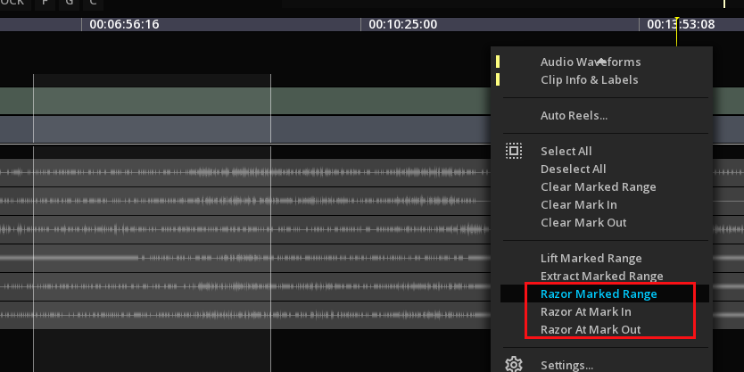
→ To modify only a particular clip, lock the other layers before performing the cut.
→ To split all the clips, including for example audio layouts not activated, select the desired layers on the Layer Control Box before applying the split/cut.
|
If you want to change effect settings over time, you needn’t split the clip; you can apply keyframes to a single clip instead. See “Understanding keyframes” section |
9.3. Joining Clips
MIST allows to join two parts of a clip, under conditions: frames must be consecutive and part of the same sequence.
→ Position the time marker in the middle of the cut and press Ctrl+J.
→ Alternatively, you can right click on the clip and select join.
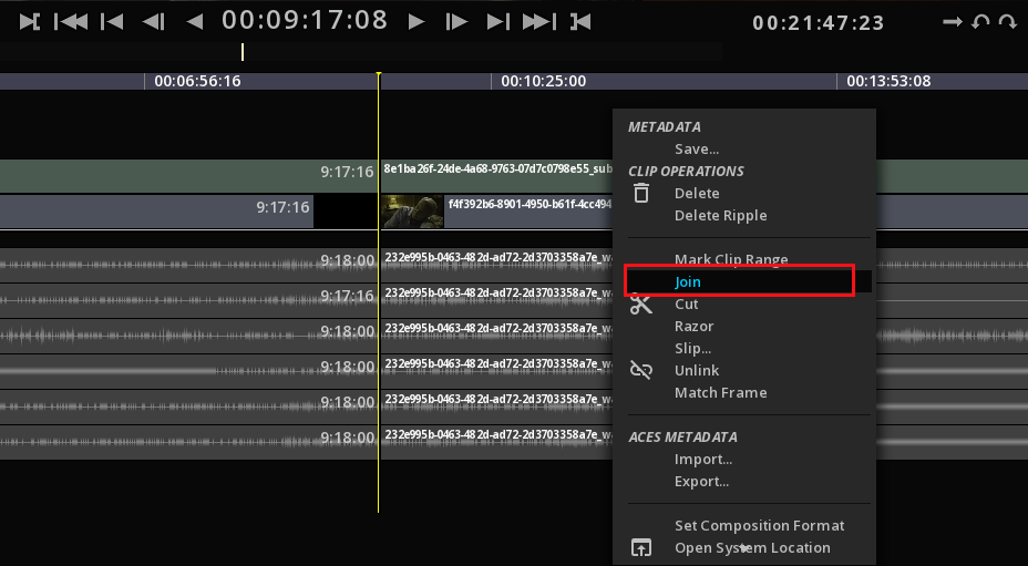
|
You can use the SNAP tool on the right top corner of the timeline or by using the shortcut W, to magnetize your selection, to the previous/next clip or to the cursor. |
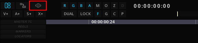
9.4. Moving Clips
All traditional editing operations are available for the clips:
9.4.1. Roll
Roll changes the Out point of one clip and the In point of the next clip. If you roll 10 frames to the left, MIST will cut 10 frames from the clip on the left and add 10 frames to the clip on the right.
→ To Roll a clip, position the mouse at the intersection of the clips until the cursor changes to  and slide on the right or on the left:
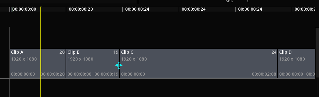
Timeline after a Roll of Clip B on the right:
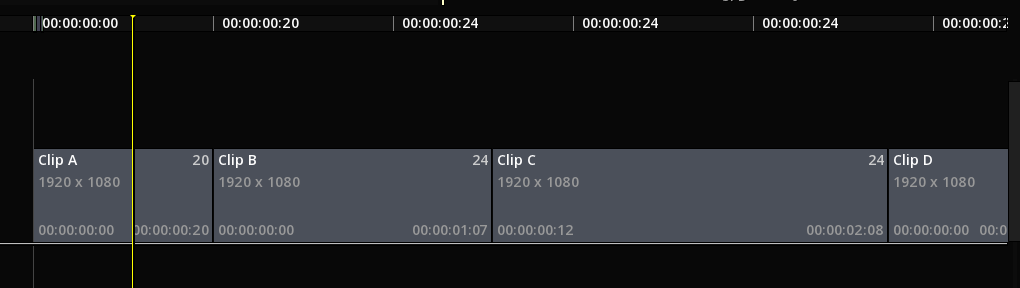
9.4.2. Trim
Performing a Trim can modify the length of a clip without modifying adjacent clips. It is not possible to trim over an adjacent clip.
→ To trim the clip, position the mouse at the intersection of the clips until the cursor changes to  or
or  and slide on the right or on the left:
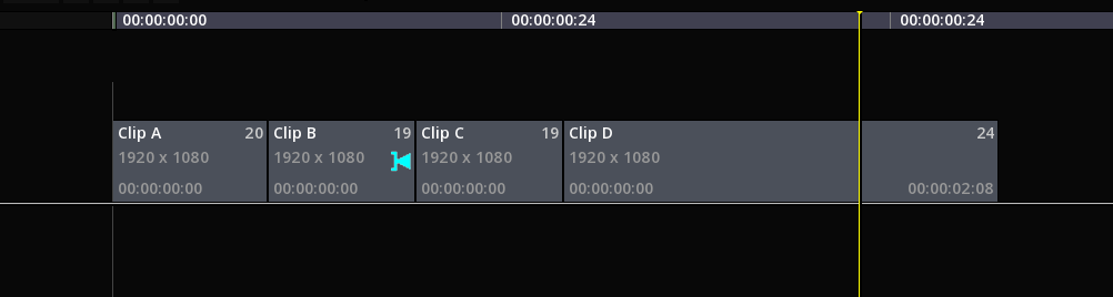
Timeline after a trim of Clip B on the left:
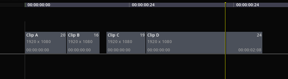
9.4.3. Slide
Moves a clip on the right or left inside an empty part of the track. It is not possible to slip over an adjacent clip.
Alt+Top arrow for + 1 frame
Alt+Down arrow for - 1 frame
9.4.4. Slip
The slipped clip’s In and Out points are offset by the same amount of frames. The adjoining clips don’t change: the media moves left or right without changing the length of the segment itself.
Select the clip to slip then use the keyboard shortcuts:
Alt+Ctrl+Left arrow for - 1 frame
Alt+Ctrl+Right arrow for + 1 frame
9.4.5. Move
You can move a clip with a simple click and drag the clip in the desired direction. The behavior on the adjacent clips depend on the mode you are in:
If the timeline is in INSERT mode, then all the clips in the timeline are moved together of the same amount of frames on the left or on the right, preserving gaps and clip lengths.
If the timeline is in REPLACE mode, the clip is moved without changing position of adjacent clips, resulting in an overwriting.
|
See more on Insert / Replace functions in next section Inserts |
9.5. Inserts
MIST allows to perform 2 types of inserts :
|
REPLACE |
The Replace will replace the frames of the composition starting from the playhead location and for the duration of the insert. By default, MIST is in REPLACE mode. |
|
INSERT |
The insert will take place at the playhead location on the composition and will lift the rest of the clips on the track to the right. |
|
When using the INSERT method, make sure to adjust the Composition duration to the new duration of the track. |
→ To toggle between INSERT and REPLACE modes, click on the icon on the top left of the TimeLine:
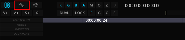
MIST allows to inserts clips on an existing Composition using 2 different methods:
-
drag & drop from the Command Panel
-
3-point editing
9.5.1. Drag & Drop Inserts
To use the drag & drop method, first select the desired insert mode (INSERT / REPLACE).
→ Position the playhead on the video track at the desired location
→ Drag & Drop your source clip from the Command Panel or the Library and use the Paste method of your choice.
9.5.2. 3-point Inserts
You can use the Dual Viewport for inserting a clip or parts of a clip using the 3-point editing method.
Refer to Dual Viewport for more information.
Inserting from playhead location
→ On the timeline of your source, place the playhead at the desired entry point and then in the timeline of your composition, place the playhead where you want to insert the media.
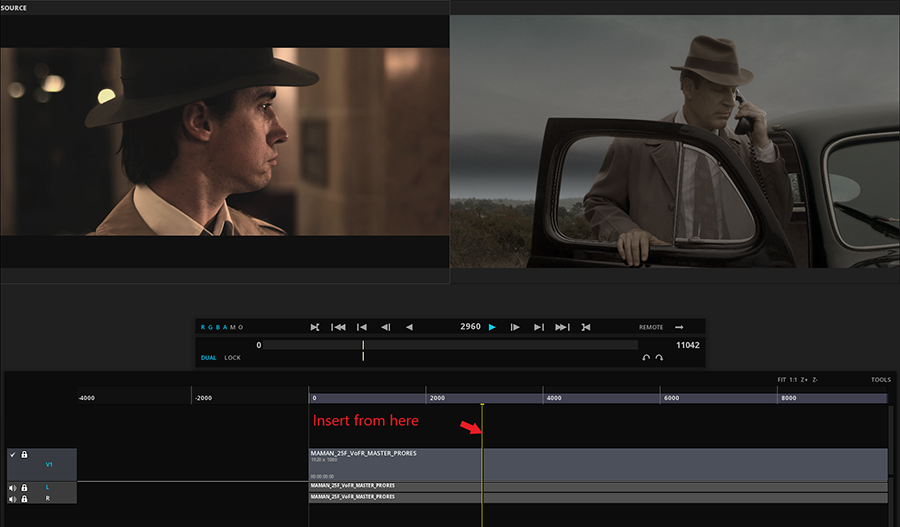
→ Define the insertion method by clicking the INSERT / REPLACE button on the Timeline and then use the Y key to insert your clip.
Your clip will be inserted from the designated entry point until the end of its duration.
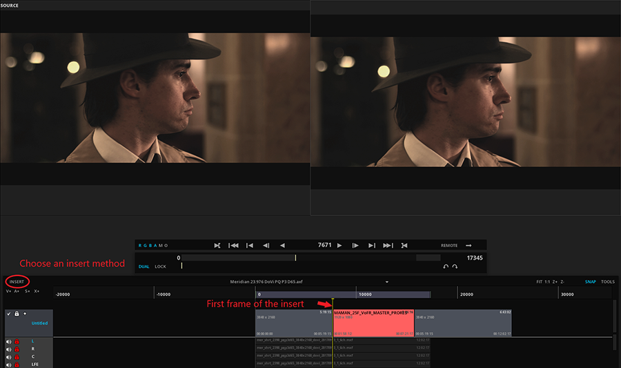
→ to insert the entire clip, place the Playhead at the biginning of the clip.
|
Do not forget to check that the track on which you are going to paste your clip is the one that is active (in blue). You can also lock your other layers to avoid errors of manipulation. |
Inserting a marked region
First start by marking the region to import on the source timeline using In and Out markers:
→ With the playhead at the desired position use I for IN and O for OUT points or use the buttons of the Transport bar.
→ Define the insertion method by clicking the INSERT / REPLACE button on the Timeline and then use the Y key to insert your clip.

10. EXPORTING MEDIA
MIST allows to export media in different ways according to the expected results.
A composition can be rendered, as well as single essence files.
10.1. Export of a Composition
When exporting a composition, all the properties of the composition are taken into account for the render: resolution, frame rate, CMS, Time Code and are reflected in the output file.
| Using the Master Delivery |
MIST will render the composition on the timeline according to the format or the delivery specification chosen. |
| Using the EXPORT menu |
A composition can be exported in several formats: AAF, FCP XML, OpenTimeline IO are part of the supported formats. |
10.2. Export of an essence file
A single essence file like a video, a subtitle or an audio file can also be exported:
| Using the EXPORT menu |
This Export mode allows to render the active subtitle or the active audio configuration of the current composition in a variety of formats. |
| From the media bin |
A quick and easy conversion of the source file directly from the media bin. The properties of the source media are applied to the output format. |
11. CONFORMING
Conforming is a step that is sometimes necessary, in many and varied situations: reconnecting an off-line editing, connecting the subtitle tracks or the image sequences to their original files etc. This is also useful in case of media present in the timeline, but which have their source deleted from the project media bin.
The application allows to manage this crucial function with numerous options.
11.1. Conform an AAF and a XML file
Once the AAF or the XML file has been imported using IMPORT on the menu bar, a timeline appears with red unlinked medias, as shown below :
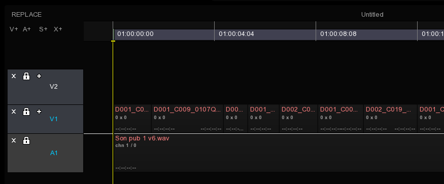
If the media is already present into the project media bin, it will be linked automatically.
|
When importing an XML or an AAF, the tracks could be imported as invisible. Be sure to have the track visible: |
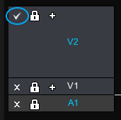
|
When a composition is loaded, by default the Playhead is positionned at TC 00: 00: 00: 00. To go to the first frame of your content, press the "Home" key, to make the playhead positioned at the entry point of the composition. |
You can access to the Conform module with a right-click on the Viewport from the Timeline Module:
→ Click on CONFORM in the menu bar to access Conforming panel.
In the conforming panel, the media of the composition appear in list form, sorted by type. A series of columns containing media information are adjustable by placing the cursor between two columns :
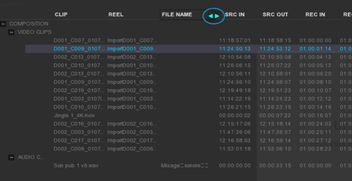
→ To move and see the remaining columns on the right of the window, just click on the slider at the bottom of the list and scroll in one direction as in the other :
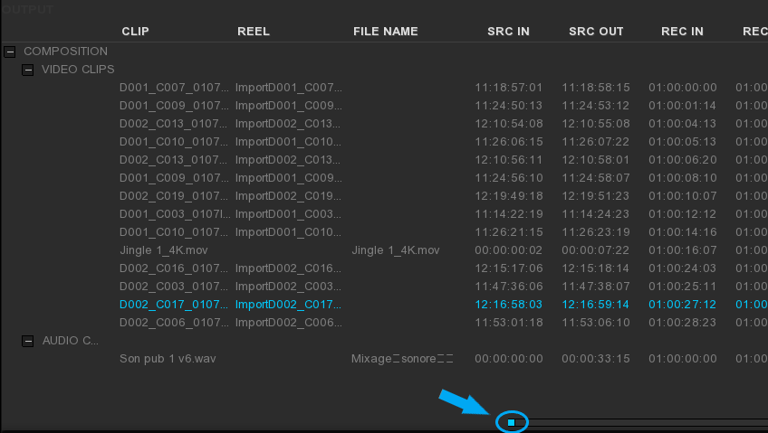
On the bottom of the panel, there is several tools used to configure how the content can be retrieved:
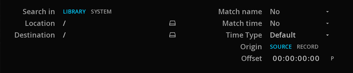
| Search in |
Choose if you want to look for media either in the project media bin (LIBRARY) or in the file system (SYSTEM). |
| Location |
Specifies the navigation path through the media either in the project media bins or system directories. |
| Destination |
Specifies the navigation path through the project media bins, in order to refer the media into the desired folder. |
| Match name |
Searches will be based on the CLIP, REEL or FILE name of the content. |
| Match time |
Searches will be based on the IN, OUT or IN & OUT timecode of the content. |
| Time Type |
Searches will be based on different types of timecode: |
| Origin |
Choose whether the previous timecode’s options are for the TC SOURCE or ORIGIN. |
| Offset |
This option allows to match one timecode with another. For example, in the case of a media whose start time is different from the one of its edit list.
|
Sometimes the conforming process requires the media to be renamed or completed in the case of missing information.
It is possible to rename the media by their Clip name, their Reel name or their File name.
→ To rename a clip, first select it in the list.
→ Enter a name and click SET:
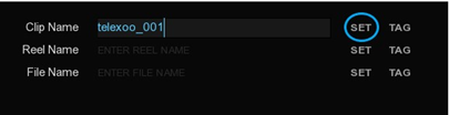
With the TAG tool, the name can be based on an existing parameter. Clicking on it displays a list:
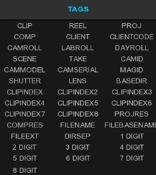
TAGs can be cumulated and added to typed text. For example, if the file name does not have existing information in its column and we want to fill it with information from the clip column, we choose the clip tag and then we type the file extension:
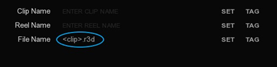
After clicking SET, the media’s FILE NAME column will be renamed:
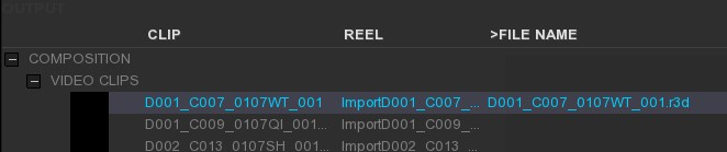
→ You can apply the renaming function on several clips at the same time: select them using Ctrl and click.
→ You can also select all the clips Ctrl+A and deselect all of them Ctrl+D.
→ Once the settings are made, click MATCH at the bottom of the module to start conforming.
After scanning, linked files should display a thumbnail as shown below:
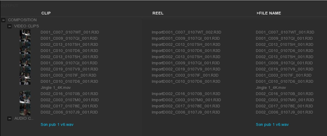
If some files could not be conformed with this first path, the operation can be repeated with any type of search without losing the previous conform.
When all the desired files are linked, just click on ESC to exit the module. Into the project media bin, the conformed medias have been referenced automatically.
11.2. The relink function
In the project media bin, if a media has been moved from the operating system, the media will appear red in the list mode or with a “media offline” information into the thumbnail of the clip.
See Relink Media
11.3. The EDL’s case
The Edit Decision List can be imported using IMPORT on the timeline:
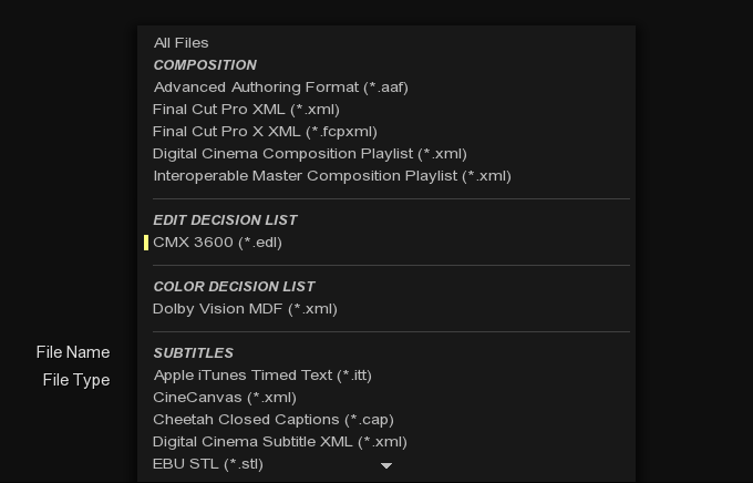
Once the EDL has been chosen, a window will appear in order to select the appropriated settings before importing. All informations about the video and audio tracks, their transition as well as the timecode presents in the EDL will be displayed as a list. A slider on the right allows to go up and down throught the this list:
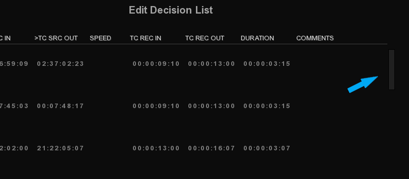
At the bottom left of the window, with the Import As drop-down menu, it is possible to import the EDL as a new layer or a new composition.
In the case of a New layer, for obvious reasons, some settings will be grayed and inaccessible. If a New composition is chosen, the dimensions, pixels and bit depth have to be setup or we can directly select a preset:
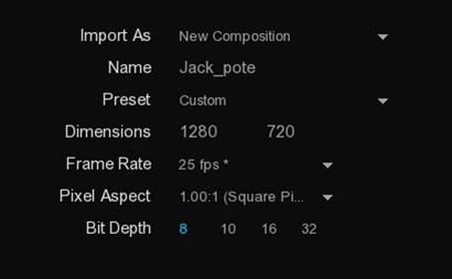
To the right, we can rename the Clip and Reel Name from the EVENT, REEL and COMMENTS columns:
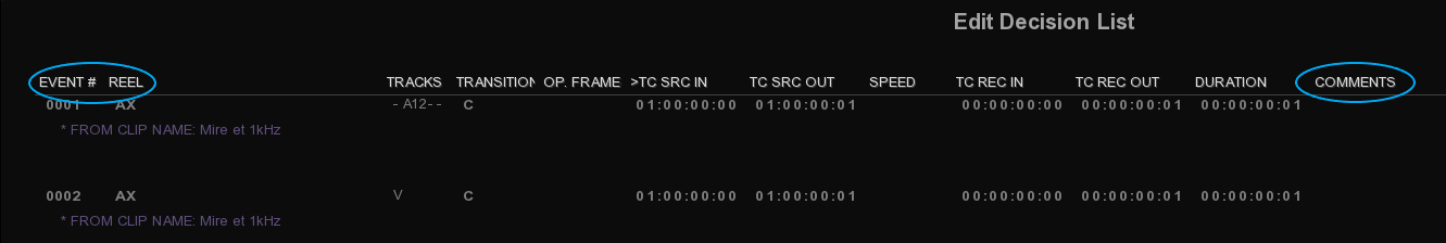
A digit padding setting is available when choosing From Event as well as we can the choice to include or not the extension when using Comment:
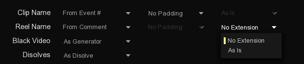
Transition management can be generated by the application or interpreted as being a clip at the discretion of the user. If the EDL contains parameters color transformations, it is possible to keep or ignore them with the ASC CDL drop-down menu.
→ Once all settings are made, click on OK.
12. ANIMATION
12.1. Overview
When grading, reframing a shot, you often need to have the parameters change dynamically over time. There are many reasons for such a need, some could be technical and some others could be simply artistic reasons. Whenever you have such a need, you must animate the parameters.
In MIST the animation of the parameters has to be done per shot. Each shot carries the animation values for all the animatable parameters. While almost all parameters can vary over time, they are organized into groups called channels. Each animation channel holds one or more keyframes that you add during the animation process. Each keyframe holds the values of the parameters associated with that specific animation channel at a specific time.
The animation occurs when you add transitions between the keyframes. Once a channel has multiple keyframes and transitions, the color correction parameters are then evaluated for each frame and the values will therefore change over time.
12.2. Acessing the animation editor
The animation editor is yet another tool that is part of the TimeLine module. It can be accessed and used at anytime without stopping you from working with the edit or grading tools. In order to start using the animation tool, you must first reveal it.
To access the animation editor, you must simply click on ANIM, located in the lower right area of the screen.

Once the animation editor has been revealed, it will be displayed at the bottom of the screen:
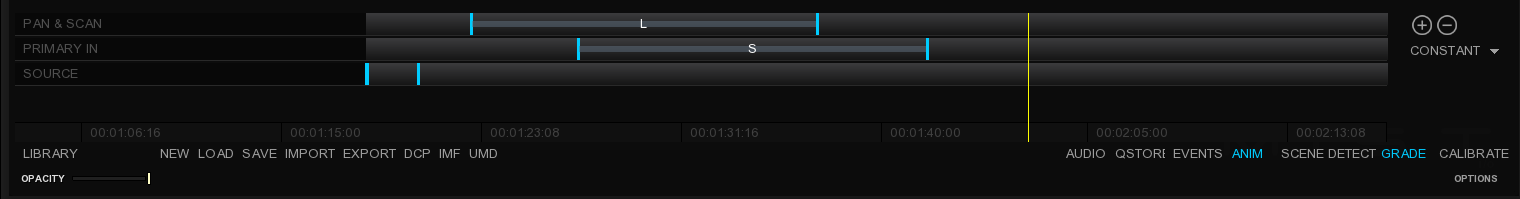
If the Event Viewer is also displayed, the animation editor will be displayed just above it.
12.3. Understanding the animation editor
The animation editor does occupy a lot of space on the screen. However it carries relevant information for the context you are in and also provides tools for the animation editing. The editor is organized in several parts, each of them dedicated to one task. The diagram below shows you this organization:
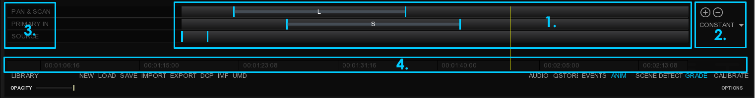
Among these four regions, region 1 and 2 are interactive, while 3 and 4 are used for information purposes only. The four regions of the editor are described in the table below:
| 1-The keyframe editor |
In here, the keyframes for the channels available in the context are displayed, together with the transition you may have between them. The editor allows you to view, add, move and delete keyframes. |
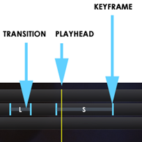
| 2-The keyframe tools |
This small part on the right provides the necessary tools for adding and deleting keyframes as well as for changing the interpolation method in a transition (constant / smooth / linear). You can change the method at any time by placing the playhead on the animated region. |
| 3-The channel labels |
The number of channels displayed in the editor may vary with the context you are in. The names of the channels currently visible are displayed in this here. |
| 4-The timescale |
This thin part of the editor shows the timescale in the same units as the timeline. This area is a reminded of the absolute time in the timeline and allows you to place your keyframes with more precision according to specific moments in the show you are working on. |
12.4. Adding keyframes
Adding keyframes is the first step to be done in order to start using the animation capabilities in MIST. Before adding a keyframe, make sure the animation editor is visible. You can add keyframes even when the editor is hidden, however if you are just starting to use the software, it can be helpful to visualize the keyframes in the editor.
Before you start adding keyframes it is important to understand how the software handles them. In MIST, added keyframes store the current state of the current animation channel. It means that if you want to change the values at a specific time via a keyframe, you must first change the parameters and then add the keyframe.
-
Use + located on the far right side of the editor or press Ctrl+Shift+K on your keyboard. By pressing this button, a keyframe is added at the current frame number. Please note that the keyframe’s position is relative to the beginning of the shot.
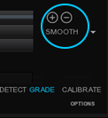
Once a keyframe has been added, you will see a little blue mark right beneath the playhead cursor.
This keyframe has stored the current state of all the parameters for the current animation channel.
12.5. Navigating across keyframes
Once you have added multiple keyframes on an animation channel, you may need to move from one to the other to change parameters and modify the keyframe or simply for deleting them. The navigation from one keyframe to the other can be done by pressing the Alt key and clicking on the next or previous cut buttons available in the transport bar.
The screenshot below shows you which buttons to use in combination with the Alt key on the keyboard:
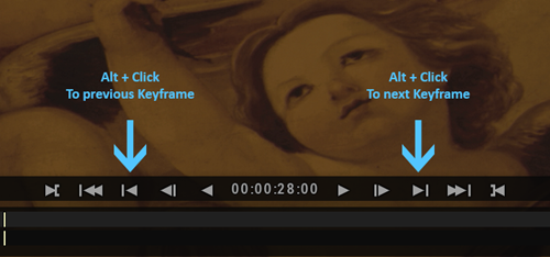
When using the keyboard, moving to the previous of next keyframe can be done with the following shortcuts:
-
Use Ctrl+Page Upto go to the previous keyframe.
-
Use Ctrl+Page Down to go to the next keyframe.
Once you have used one of the methods described above to navigate to the next or previous keyframe, the playhead will jump to the position at which the keyframe was set.
12.6. Deleting keyframes
Once a keyframe is no longer needed or inadequate (typically this situation may occur when copying grade parameters from one shot to another), it can be deleted. To delete a keyframe, you must position the playhead on the keyframe.
Once the playhead is positioned, you can use one of the following methods to delete the keyframe:
-
You must first place the playhead on the keyframe to be deleted and press - in the keyframe tools.
-
If you are using the keyboard, to delete the keyframe you need to press Ctrl+Delete.
12.7. Modifying keyframes
Keyframes must often be modified to reflect the changes in an animation. Doing so is no different than adding a keyframe. However, in order to modify an existing keyframe, you have to place the playhead on the keyframe first and then use the same method as you would use for adding a new one. The following steps describe the procedure for modifying a keyframe:
-
Just like when adding a new keyframe, the first step is to place the playhead on the keyframe you want to change.
-
The you must simply change the parameters you want to modify in the keyframe.
-
Once the parameters have been changed, use one of the following methods to apply the changes to the keyframe.
12.8. Animating color correction parameters
Each of the tools described above expose a great number of parameters. Almost all of them can be animated (for obvious reasons, parameters such as the aspect ratio or the Raw files decoding resolution or color space, cannot be animated).
The animation of the parameters is divided into logical animation channels. These animation channels control the change of values over time and interpolate values when needed (e.g. between keyframes).
In MIST, the animatable parameters are split into the following logical channels :
-
Source parameters
-
Pan & Scan
-
YRGB/Balance/Mixer/Curves
-
Auxiliary
The Source parameters are independent from other color correction parameters because they influence on the quality of the decoded image. In some situations, the decoding parameters must be animate to compensate for the lighting condition changes. This hold true even if no further color correction needs to be applied. Most of the time the temperature and tint are animated, but others can be as well. The Source parameters are grouped into the Source Animation Channel.
The Pan & Scan parameters are also independent from others because the frame adjustments are not related to color changes. Reframing and image may need animation (e.g. in the case of image stabilization) or adjusting the convergence in a Stereo3D timeline may need animation as well. The Pan & Scan parameters are grouped into the Pan & Scan Animation Channel.
The remaining tools such as YRGB, Balance, Mixer and Curves are controlled by a single animation channel : the Primary Animation Channel. When grading, these parameters are often adjusted at the same time for the same reason and therefore they are grouped together.
Finally the Auxiliary tools (such as OpenFX plugins or DVO’s) are animated independently, when possible. Please refer to their documentation to know more about which parameter can be animated.
|
Clicking AUTO on the far right of the GRADE panel, before making any changes, to automatically create new keyframes. |
13. SUBTITLES & CAPTIONS
MIST is able to import and manage a wide range of subtitles and captions for the broadcast and film industries. To see the full list of formats supported by MIST for import and export, please refer to the Appendices Supported Input formats and Supported Output formats.
In the following section, we will see how to import, inspect, manage, and export subtitles and captions.
13.1. About Subtitle Management
The way subtitles are managed by the application depends on the format but there is some common behavior.
13.1.2. Subtitle File Duration
It is important to differentiate the effective duration of the subtitle file from the interpreted duration.
The effective duration is ranging from the first spot to the last spot. Whatever timecode is indicated for the first spot, once placed on the timeline the interpreted start will always be 0:00:00:00 by convention unless otherwise specified in the metadata.
If a start TC is embedded in the file, for example an EBU STL file starting at 10:00:00, then the way it will be interpreted by the timeline differs depending on the way the file is opened:
If you double click on a subtitle file specifying a start TC directly in the media bin, it will be placed automatically on the timeline at the indicated Start TC:
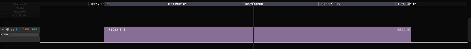
If you import a subtitle file specifying a start TC on an existing timeline using drag & CTRL V, then the start TC will be the one of the playhead location:
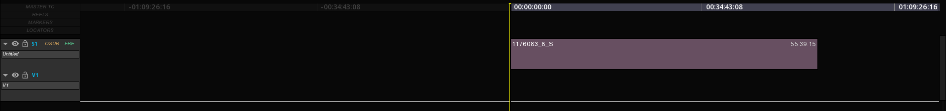
In this last case, the original TC of the spots will be relative to the new start point of the file. This will be reflected in the spot list with a different color for the time codes (see below Subtitle Inspection chapter).
13.1.3. Subtitles metadata
Some subtitle formats carry metadata that are displayed in the page.
When you import the file on a new subtitle track on the timeline, the track box will display the language information present in the file. However, if you delete the file and replace it with another clip of another language, the Track language information will not be updated automatically.
13.2. Import subtitles and captions files
It is possible to import text subtitles and graphic subtitles. A type of track is dedicated to subtitles files on the top of all the video layers in the composition.
13.2.1. Import text profile
The import of standalone subtitle file is similar to a video or a audio assets.
You can import the subtitle file directly from the OS browser by selecting it and dragging it into the Command Panel's Media bin.
13.2.2. Import image profile
The way to import subtitles and captions image profile is identical to text profile.
However, make sure the image files and the subtitle XML file are in the same root folder, permitting to automatically locate the image files to which the XML subtitle file refers.
13.2.3. Place a subtitle file in a composition
→ To place your subtitles and captions in the timeline create a subtitle track by clicking S+ at the top left of the timeline and place your media like any other asset type or paste it directly to the playhead location.
In case you have selected multiple subtitle tracks, they will be stacked on the top of each other.
13.2.4. Displaying multiple subtitles
The way mutliple subtitle tracks are displayed depend on the mode of the composition:
-
in VERSIONING mode, only the top track will be displayed.
-
in COMPOSITING mode, all tracks will be displayed simultaneously
If needed you can hide a track using the Enable / disable icon (eye).
13.2.5. Set the composition format according to the subtitle
It is possible to configure the composition size according to the properties of a subtitle file such as IMSC1. To do this, the file must have the attribute tts: extent defining the resolution of the image in its settings.
Most of the time, this attribute is used in the subtitle files using the image profile and the pixel unit. This is to inform the optimal resolution of the use of the subtitle, so as not to deteriorate its quality which the would make it unusable:
-
From the subtitle track, right-click on the subtitle file.
-
Click on Set composition format.
The composition fits the dimensions of the subtitle file.
In the case of using a subtitle in text profile, the subtitle will use the same resolution as the current composition. The text being vectorial, there is no loss of quality.
13.3. Inspecting subtitles
Once a subtitle has been loaded on the timeline, it is ready for inspection.
The subtitle file can contain one or more blocks of text, each block itself being able to contain several lines of text. Each block has several properties, including the font face type, size and of course the start and end time during the presentation.
13.3.1. Browse subtitles using the spotlist
It is possible to quickly navigate from one subtitle line to another one in the composition.
→ Go to
→ Double click on a timecode REC IN or REC OUT :

|
If the Timecodes in the spotlist are displayed in yellow, it means that they have been adjusted from the original source timecode to match the actual composition. |
13.3.2. Inspecting Subtitle Placement
On the Viewport you can activate different Guides in order to verify the placement of a subtitle on the image:
→ Display the Safe Frame guides using Alt+F.
Parameters for the Safe frame guide can be adjusted in
→ Display a grid on the Viewport using Alt+G.
13.3.3. Loading manually a font
As soon as the subtitle has been placed in the timeline, subtitles are displayed into the Viewport. If not, verify that the associated font has been loaded:
→ Go to
If a font is present in the subtitle, it’s name will automatically appear under the tab FONT in white color.
|
A subtitle file can have multiple fonts referenced into the list. |
If the font has been not properly loaded, no font will be listed or the font will be displayed in red.
In addition, the Console will display an error message:
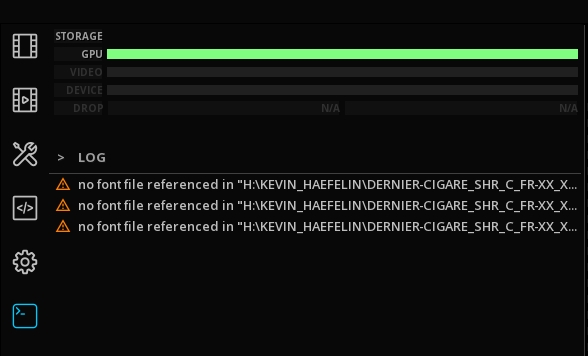
→ Double-click on the 1 digit or the font label to open the Font Library.
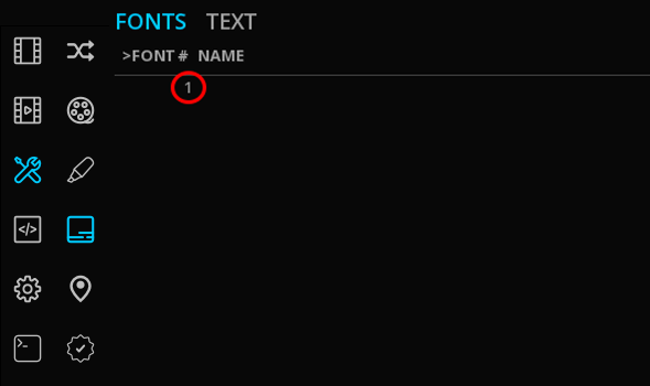
→ Select the desired font into the list and click on OK to validate your selection. Fonts present in this list are based on the OS font folder.
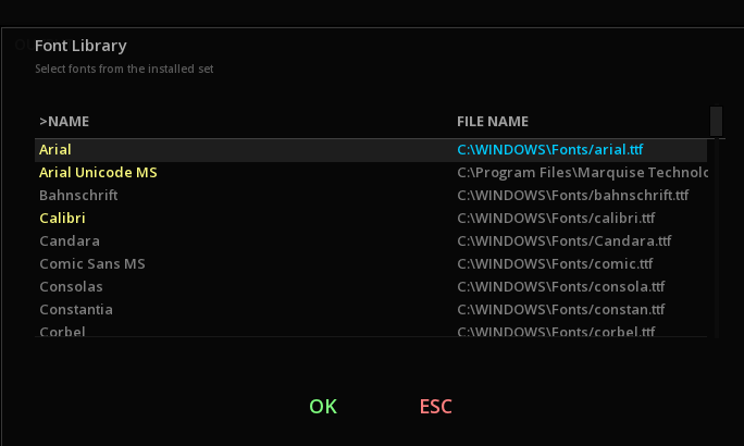
|
TrueType fonts ( |
|
In order for a font associated with a subtitle to be automatically loaded, the font file must be in the same root folder as the subtitle text file. Otherwise, the Arial font is loaded by default. |
13.4. Editing subtitles
13.4.1. Editing the subtitle track
Due to the inherent structure of the subtitle file, MIST imports subtitle files as a single block with all your text into it. Like any other type of media, it is possible to apply basics editing functions.
When you cut a subtitle file placed in the timeline, the REC In and REC Out will be displayed in yellow in the spotlist. The spotlist is located in the TEXT tab of the SUBTITLES panel.
This indicates the offset value between each line of text subtitles with the timecode of the cut as starting point. Regardless of the placement of the subtitle cut in the timeline, the indicated offset will always be based on the timecode registered in the subtitle file.
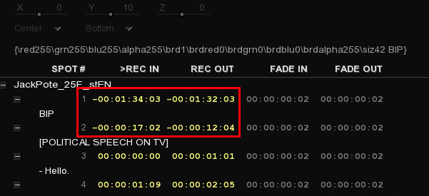
13.4.2. Editing of subtitle text
MIST allows a large modification of many subtitle and caption parameters through inline commands. The possibilities of modifying these parameters depend mainly on the format of the subtitle in use.
If you want to do some basics text editing correction, do as follow:
-
First, select the subtitle text line to modify (not its timecode line).
-
Click the text field in order to be able to edit it:
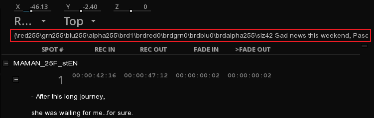
-
Edit the text from the inline command.
For DCI subtitles format, it is possible to change the text position by moving respectively the X,Y and Z sliders from left to right to change the values. From the drop-down menu, select the desired text alignment.
13.4.3. Editing subtitles for stereoscopy
Subtitle management for stereoscopy is similar to subtitle management for other content. The main difference is to care of the Z axis when editing subtitle position in the TOOLS tab. There is no need to duplicate tracks to generate 3D for subtitles.
To manage the Z axis, do as follow:
-
Be sure to use the 3D mode in the composition settings.
-
Open the Text tab from the SUBTITLES tool (
Alt+F2). -
Select a 3D view of your choice from the Viewport Hot Box such as S3D AG Gray so you can adjust the depth of your subtitle.
-
Move the cursor of the Z axis accordingly.
For further information, please report to the stereoscopy chapter.
13.4.4. Defining a language & a type attribute
As seen in previous sections of this chapter, if the language information is present in the file’s metadata, it will be applied to the track on the timeline.
However these informations can be modified when creating a master, in the Timed Text section of the Master Delivery panel.
13.5. Export subtitles and captions
13.5.1. As a new subtitle file
MIST allows you to export your subtitle track to another subtitle format as single file:
→ Select your subtitle track by making it active (track name highlighted in cyan).
→ Click on EXPORT to open the export window.
→ From the File type drop-down menu, select the format to export from the Subtitles category.
→ After having define your file path, click OK to export the subtitle.
Note that for some file format, the font can be added to the subtitle file (e.g. CineCanvas).
|
The export process doesn’t take in account the use of reels.The contents of all reels get merged in the same file for output. |
|
This file export takes into account the parameters of the composition: TC, frame rate, etc. To export the subtitle using the source parameters, see Export a Subtitle from the media bin. |
13.5.2. Export using the Master Delivery
See also more on Subtitle export in the Master Delivery chapter.
For HDR content
MIST allows to manage the color space and the luminance gain independently from the video track.
Read the MTCMS chapter for further informations.
Export subtitles and captions into an IMF
MIST allows subtitles and captions to be included in an IMF package. Please refer to the IMF chapter for more information.
|
An IMF can contain both image profile and text profile subtitles, provided that each profile uses a separate subtitle track. For now, it is not possible to mix the two profiles on the same subtitle track. |
Export subtitles and captions into a DCP
MIST allows subtitles to be included and encrypted in an DCP package. Please refer to the DCP chapter for more information.
|
Unlike the IMF, a subtitle track can contain both a subtitle using image profile and another using text profile. |
Burning of subtitles and captions via the Master Delivery panel
When exporting a content using the Master Delivery panel, except for iTunes packages, if you select a Burn in the active subtitle track will be automatically rendered. Subtitles must be visible to be burned in. Other subtitle tracks are ignored.
|
The Burn-in option is only available if the timeline is set on COMPOSITING mode |
13.5.3. Export a Subtitle from the media bin
From the media bin, right-click on a subtitle file and choose Export as…
→ From the File Type menu choose the desired subtile format, choose a location and validate with OK.
This action will perform a subtitle conversion taking into account the source clip properties (TC, frame rate).
14. AUDIO MANAGEMENT
14.1. Audio in the TimeLine
Audio tracks and channels are reprensented in the Timeline as they are in the file.
The timeline allows an infinity of audio sounfields and individual audio channels.
Example of a composition with 2 soundfields:
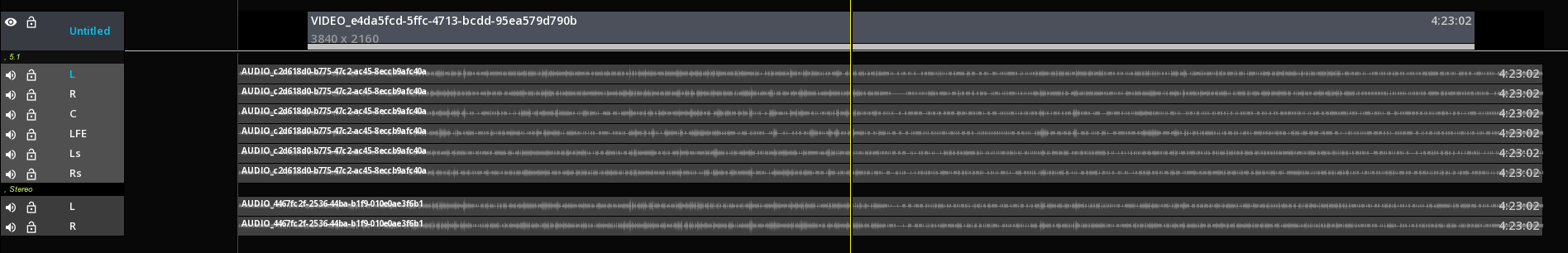
14.1.1. Display Audio Waveforms
→ press Right mouse button on the TimeLine background to display the Composition drop-down menu and select Audio Waveforms:
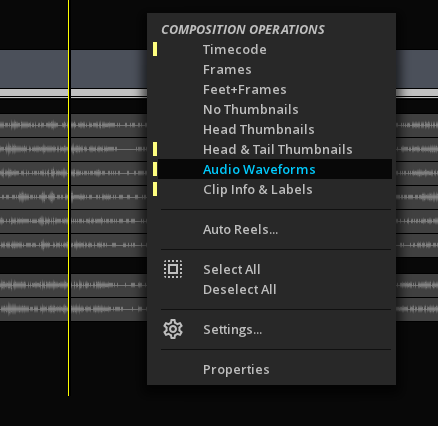
14.1.2. CLip Audio Channel Remapping
If the channels of an audio clip have been incorrectly mapped, it is possible to remap them automatically in the timeline:
→ Click on the audio channel to remap then use right mouse button to display the Clip drop-down menu.
→ in Channel Mapping, select the new channel to assign:
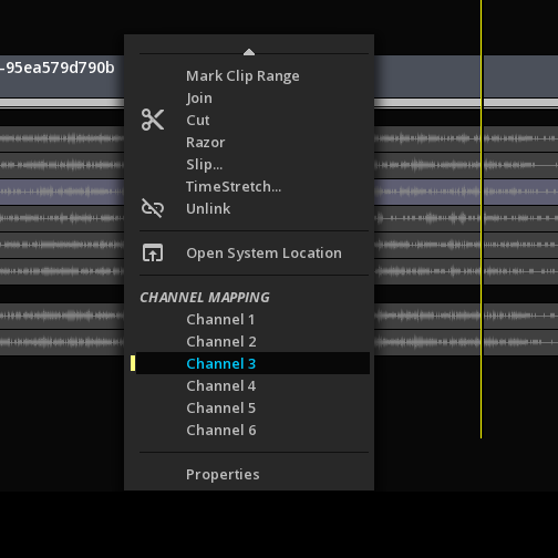
You can verify the channels assignement of the clips when the audio lanes are extended:
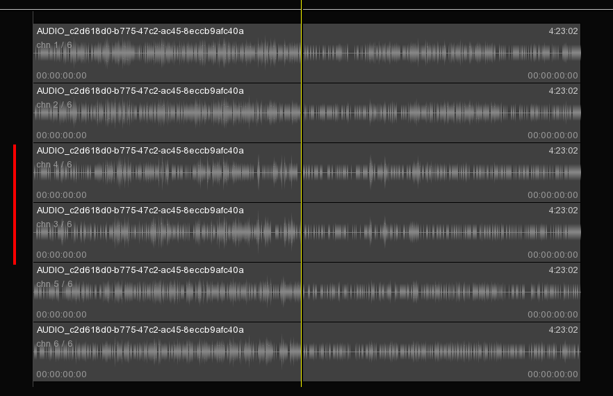
14.2. Audio Monitoring
In MIST, the audio is outputted on both the video IO card and the PC sound card.
When the PC sound card is used, if the system ressources are low, some images may drop to follow the sound.
When using the video IO, audio and images are guaranteed to be in sync.
Different tools like audio routing, down-mix and Audio meters are available for the QC of audio tracks.
14.2.1. Audio Routing
To route the audio channels:
→ In the Command Panel, select TOOLS then ROUTING
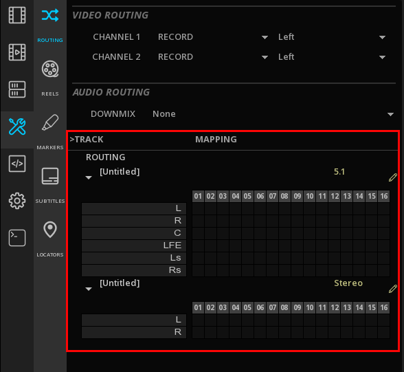
If several soundfileds are present on te timeline, they will be displayed in the Routing panel in the same order.
→ To expand / collapse a soundfield, click on the triangle:
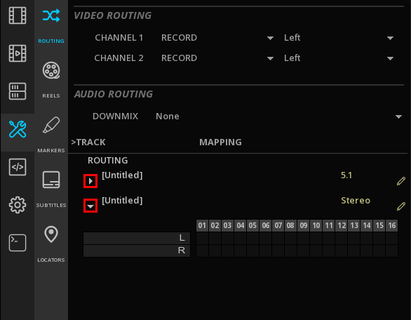
→ Assign the audio layers of all the soundfields present on the timeline to the desired audio channel (up to 16) by a click in the cell:
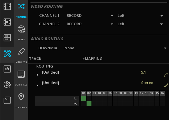
→ To change the channel assignment, click on the desired channel for each audio layers.
14.2.2. Down-Mix
If your listening device is not compatible with the soundfields on the timeline, it is possible to perform a down-mix to stereo:
→ In the Command Panel, select TOOLS then ROUTING
→ In the Audio Routing section, use the DOWNMIX dropdown menu to select the desired downmix configuration:
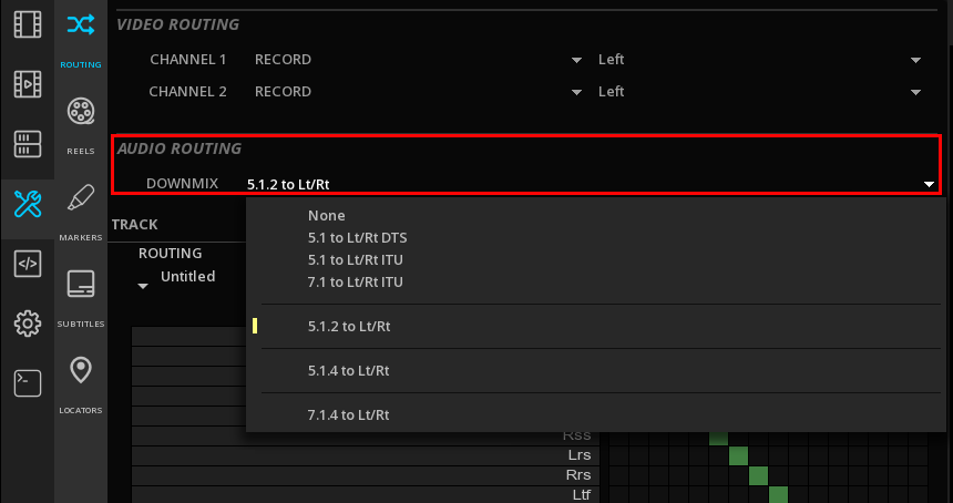
14.2.3. Audio Analysis
MIST offers a full set of Audio monitoring tools for the quality control. Refers to the chapter Audio Monitoring for details about the different audio scopes.
14.3. Audio Time Stretch
It is possible to perform a Time Stretch on the audio clips, when their original framerate does not match the output settings.
For example you receive a Master at 23.97 and you need to create a version at 25 FPS.
→ Select the audio clip(s) on which you want to apply a Time stretch then right-click. In the drop-down menu choose TimeStretch:
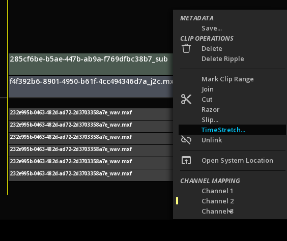
→ Indicate the Source format and the Destination format and validate with OK:
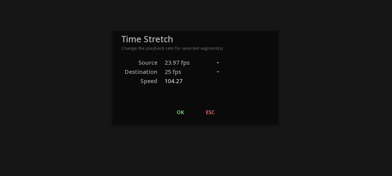
Once the timestretch has been applied, the audio clips are displayed in green:
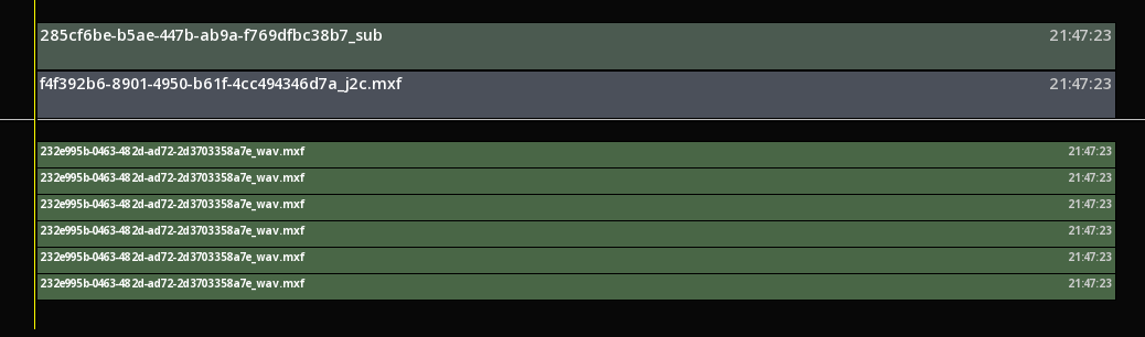
The playback and the render will then be done using this new frame rate.
14.4. Immersive Audio
14.4.1. Importing Immersive Audio files
In MIST, the Immersive Audio files are not managed as regular audio tracks.
When dropping an immersive audio track into the Media bin, MIST recognizes the metadata and displays a specific icon for the file:
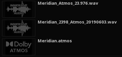
When importing manually clips, the immersive audio files must be placed on an Auxiliary data track on the timeline.
|
if MIST has detected immersive audio metadata in the file, it will prevent the drop of the file on a regular audio track. |
-
Create a new Auxiliary data track by clicking on the X+ button on the left side of the timeline:
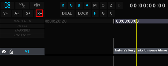
In the drop down-menu, select the desired type of Immersive audio track:
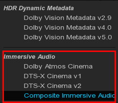
A new layer has been added to the timeline:
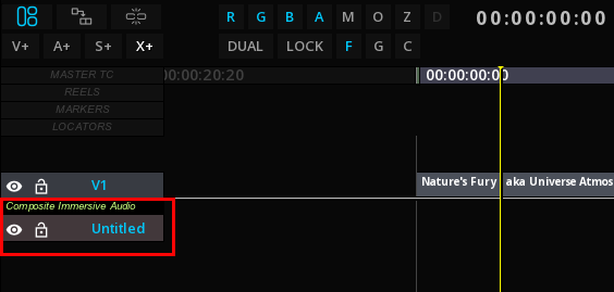
You can now place your immersive audio track on the timeline.
|
A double click on the file in the media bin will immediatly open the file in the timeline at the right frame rate and time code configuration. |
14.4.2. Dolby Atmos
MIST supports Dolby AtmosTM technology and allows the import and the render of Atmos files for QC purposes.
Supported Formats
MIST supports the following Atmos formats:
-
DAMF (Dolby Atmos Master Format)
-
BWF ADM (Broadcast Wave Format with Audio Definition Model)
-
IAB (Immersive Audio Bitstream) for DCP (including encrypted files) and IMF
These files can be imported in the timeline as stand-alone files or wrapped in an IMF or a DCP package (IAB).
|
When importing a DAMF in stand-alone, select in the directory the file with the extensions .atmos and drop it into MIST: 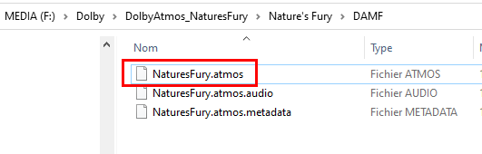
|
Importing Dolby Atmos files
Proceed as mentioned above in the section Importing Immersive Audio files.
-
If your Atmos file is mastered for Digital Cinema, in the Auxiliary Track drop-down menu select Dolby Atmos Cinema
-
For any other type of Atmos file, use Composite Immersive Audio
The layer will be created with the audio configuration set by default (2.0, 5.1, 7.1 or 7.1.4).
|
To change the default audio configuration, go to |
Dolby Atmos Rendering
It is possible to render (playback) all supported Atmos files through the integrated Dolby Atmos Renderer, to the exception of encrypted IAB files for Digital Cinema Package.
The Dolby Atmos Renderer permits the following channel based audio outputs:
-
2.0
-
5.1
-
7.1
-
5.1.4
-
7.1.4
The rendering is defined by the default audio configuration, but this can changed on the fly in the Command Panel, TOOLS, ROUTING, Audio Routing.
-
click on the audio configuration Edit icon to display the drop-down menu and change the configuration:
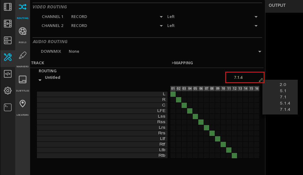

Dolby Atmos Room visualizer
The Room visualizer allows a real-time 3D visualization of the immersive audio objects positions in the room.

See Audio Monitoring to display the Room meter.
Dolby Atmos Files Export
MIST allows to export Dolby Atmos content in a variety of files and packages:
-
Export of Atmos in an IMF App2e and TSP 2121 (IAB)
-
Export of Atmos for iTunes (BWF ADM)
-
Export of Atmos in DCP (see DCP with Dolby Atmos)
-
Export of a downmix of the Atmos file into our supported deliverables (see Deliver)
14.4.3. DTS-X
MIST allows the wrapping of DTS-X audio tracks in a DCP. See Creating a DCP with DTS-X.
15. COLOR MANAGEMENT
15.1. About Color Management
The Color Management System defines the working color space of the composition (also referred as Workflow), regardless of the source color space or the desired output color space.
- Source color space
-
The color space used to encode the source media. Depending on the format, the color space may be available as a metadata. If so, it will be automatically identified.
For example, if a content in HDR is loaded in the timeline contains HDR color space information, the viewport will display the HDR10 logo. In some cases, like working with image sequences where no color space information is carried in the files, it will be necessary to define it manually. - Workflow
-
The color space of the composition itself. It can be the same as the source or not. By default if the source color space is identified from the format metadata, the composition will automatically reflects it in the viewport.
Numerous tools are linked to the workflow chosen, like the image scopes which scale will be automatically set according to the active workflow.
The workflow can be a custom one, where the user chooses the color primaries and the EOTF, or a Preset where all the parameters are already set for working in SDR, HDR or for the Digital Cinema.
|
It is possible to mix the color pipelines within the same project, however a composition can only use one workflow at a time. |
- Output color space
-
The output color space behavior depends on the type of workflow chosen, (the composition) and not on the source color space.
MIST allows to set a different Output Color space when rendering the composition. If any color space conversion is required for the output, it will be done from the workflow settings, and not the source settings. See Master Delivery.
15.2. Available Color Management Systems
There is 3 types of color management systems available:
| Native |
The color space of the source is used as is and no color space conversion is applied on the output. |
| MTCMS |
The Marquise Technologies CMS is used to perform advanced color conversions. |
| ACES |
Allows workflows in Academy Color Encoding System. |
15.2.1. Native CMS
Using the Native CMS, the media is displayed as is and no color space conversion is done on the composition.
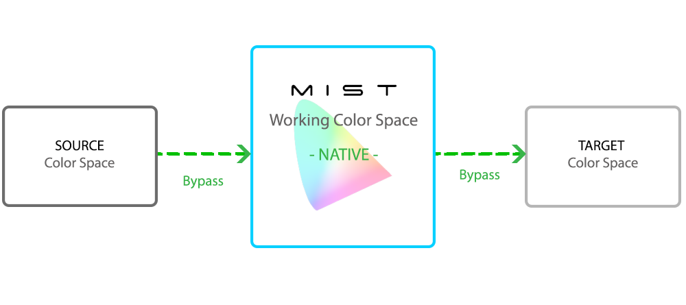
The native CMS is particularly recommended when the media is already in the right color space and finalized after the grading phase.
With this mode it is however important to set the Worklfow accordingly, in order to have the full tool set of image analysis in line with the content.
15.2.2. MTCMS
The Marquise Technologies' Color Management System is a proprietary color management system allowing state of the art color conversions.
For more precision and reliability, MTCMS uses industry standards to compute in 32 bit-float on-the-fly the exact values for every possible color. No interpolation is done when using a LUT.

|
Using MTCMS, it is necessary to indicate what are the color parameters of the source media, in order to be able to perform the accurate color transformation. See Source characterization |
15.2.3. ACES
ACES, for Academy Color Encoding System, has been developed by AMPAS (Academy of Motion Picture Arts and Sciences) with the intend to help preserve the color integrity of the content from shooting to archiving.
Specific algorithm allows any kind of source to be processed within the controlled environment of the ACES color space and for a specific output.
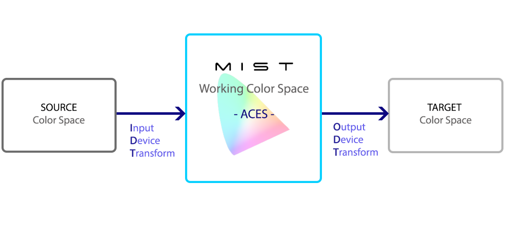
For additional information on ACES, please refer to the ACES White Paper document.
Input Device Transform
When selecting the ACES CMS, MIST inspects the media metadata to automatically set the right IDT.
However it is always possible to modify manually the IDT.
There is a non exhaustive list of IDTs avaialble in the drop-down menu, including the ones defined for cameras and a list of main inverse ODTs.
→ From the GRADE PANEL in the Source tab, choose the IDT corresponding to the properties of each of your clips.
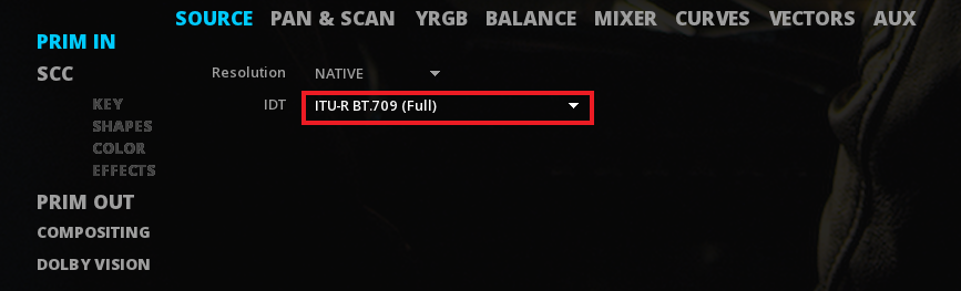
Output Device Transform
In ACES system, you need to choose an Output Device Transform to display properly your content. ODTs are defined for standard outputs only not specific pieces of equipment.
The ODTs are chosen in the Displays / Target Display drop down menu
15.3. CMS Settings
The CMS is chosen in the Command Panel, Composition Settings.
| SySTEM |
Select the Native, MTCMS or ACES system |
| Workflow |
Define the Color space of the composition:
|
| Adapatation |
Select the chromatic adaptation. See chromatic adaptation |
| Dynamic Tone Mapping |
Select the version used for Dolby Vision metadata. See Dolby Vision. |
| Safe Gamut |
Defines the color space used for marking safe boundaries in the scopes. |
| Min (cd/m2) |
Defines the minimum authorized luminance in nits used in the Zebra scope, or the HDR Report. |
| Max (cd/m2) |
Defines the maximal authorized luminance in nits used in the Zebra scope, or the HDR Report. |
| Content Light Levels |
Max FALL and Max CLL information can be manually entered here, if the media does not carry that information. |
| Timed Text Color Space |
MIST allows to manage the subtitle luminance independently of the one of the video track. This setting is applied only in the case of an HDR composition (i.e working in a HDR, HLG or Dolby Vision workflow) and using the MTCMS system. |
| Timed Text Gain |
By default, a factor of 4 is applied in MIST (e.g. a 100 nits subtitle will appear at 400nits.) It is possible to check the luminance of the subtitles using the waveform scope. |
15.3.1. Source Characterization
As explained previously the CMS requires to define the colorimetric information of the sources placed on the timeline of the composition for reference for all future operations (e.g. conversions, color-grading, exports, etc.). Source settings can be managed individually by clip.
MIST parse the existing metadata of the media, so when a color metadata is present in the file, MIST will automatically load it as Source settings. If not, you need to characterize the source manually.
→ Access the GRADE panel at the bottom right of the timeline (or press F9)
→ Select the clip(s) in the timeline
→ In the Source tab, select the source parameters.
→ To use the same settings on all the clips, select them on the timeline then use the GANG function.
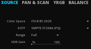
From one CMS to another, the required information may vary slightly:
-
Source parameters in MTCMS mode:
| Color Space |
Select the source color space from the drop down menu |
| Gamma |
Select the EOTF (Gamma) used for the source media from the drop down menu |
| Range |
Choose the range (Head or Full) from the drop down menu. For more information about the range, see Color Range |
| HDR Gain |
When converting SDR to HDR content, the HDR Gain is used to raise the levels of an SDR source. The percentage gain corresponds to its equivalence in nits (e.i 100 nits = 100%).
|
15.3.2. About Color Range
MIST always compute in FULL range internally meaning that:
-
If HEAD range is selected, MIST will scale the legal range to fill the FULL range.
-
If FULL, range is selected, MIST will keep the native range of the media.
That’s why if no information of range is present in the media, the FULL range will be set by default. This avoid any additional compression if the source is indeed encoded as FULL content but with no metadata saying.
Be careful with this setting or your output may have levels that are not correct.
|
Use the Histogram ( |
15.3.3. About Chromatic Adapatation
MIST supports different chromatic adaptation also called Color Appearance Model (CAM). This adaptation makes it possible to match the original RGB color coordinates of the DSM to equivalent CIE XYZ coordinates. These colors are not matching from a colorimetric point of view but rather from a perceptual point of view. This is why MIST offers different methods that will meet the needs of each project. Select a method to apply for adapting the white point of your source media to the one set in the MTCMS:
| XYZ Scaling |
XYZ Scaling is an old algorithm generally considered to be less efficient than the new ones. |
| Bradford |
Bradford is most advanced than Von Kries and XYZ. Because of the varying color constancy of the samples, the algorithm was designed so that corresponding colors represented the same appearance under the different illumination sources, and not necessarily the same sample. |
| Von Kries |
The algorithm assumes that chromatic adaptation is indeed an independent gain control of the cone responses of the human visual system and that the scaling is based on the ratio of the cone responses of the illuminants. |
15.4. Displays
Mastering Display, Target Display and Viewport Display settings are available in the Command Panel, Composition Settings.
15.4.1. Mastering Display
Setting the Mastering Display for HDR workflows
When working in HDR, the Mastering display is used to describe the capabilities of the display used to master the content : CIE (x,y) chromaticity coordinates for RGB primaries, White Point, and min/max luminance of the mastering display.
The characterization of the mastering display based on the SMPTE ST-2086 standard is a key element when working in PQ (ST-2084) and Dolby Vision. These statics metadata are critical for HDR mastering & QC.
ST-2086 metadata is stored per composition, so in a project with multiple compositions, you can have different metadata settings for the mastering display.
If the Mastering Display information is already present in the media, then MIST will automatically display it.
However this parameter can be manually modified, using the list of preset including the most common HDR monitors.
-
Use Custom to define your own monitor characterization.
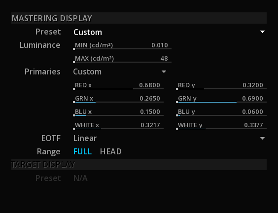
Setting the Mastering Display for a connected device
MIST can control some display device via their proprietary protocols to send the right metadata and avoid forcing the users to use the monitor menus.
When loading a composition (or changing its settings) MIST will communicate the parameters to the display.
-
Select a Preset:
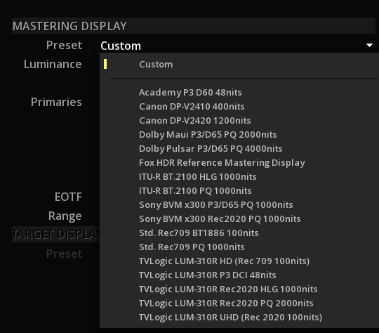
The list of presets varies according to the CMS workflow chosen.
|
If the monitor list is empty, it might be a problem of Windows ‘access rights on the folder. In order to fix it, go to the MIST folder, right-click on the displays folder and go to Properties then Security to give the Full control. |
|
Do not confuse the Mastering Display of the composition settings for ST-2086 metadata with the Mastering Display parameters in the Projects settings, allowing to configure the communication between MIST and the reference monitor. |
|
If your monitor is not in the preset list, you can create one by using an existing sample in XML and edit it. This XML has to be place in : \program files\Marquise Technologies\MIST\resources\displays |
15.4.2. Target Display
The Target Display allows to select the way the content will be displayed in ACES CMS or for Dolby Vision workflows.
Dolby Vision Target Displays
See Dolby Vision
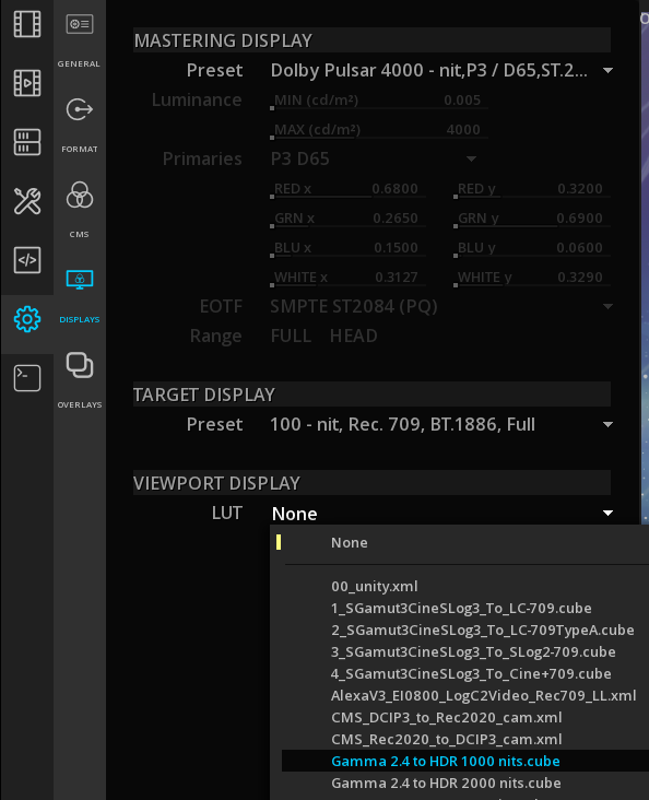
16. ANALYSIS TOOLS
MIST has a full sets of analysis tools, for the image, the audio and also the content bit rate.
It can also load 3rd party QC reports.
16.1. About the scopes
A variety of scopes are available for image and audio analysis.
You can access the scopes and meters using the Viewport menu: On the viewport, right-click to display the menu and select the desired scopes:
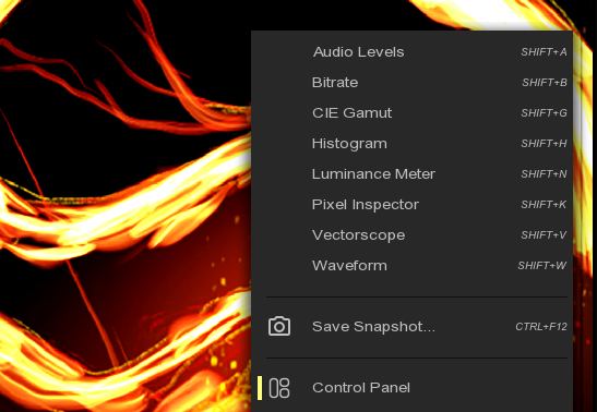
→ Alternatively, you can use the keyboard shortcuts for each scope.
Each scope can be shown or hidden independently.
They can be moved and resized across the entire application window at the operator’s convenience.
→ To adjust the size of the scopes, position the mouse cursor on the corner of the panel and use click & drag up or down.
→ To move the scope, position the mouse on the scope panel and simply click & move.
→ To modify the scope transparency, use the OPACITY scroll bar
→ To display the scope' OPTIONS, right click on the scope. This will open the options' menu. Click anywhere outside the menu to close it.
→ To close a Scope, click CLOSE on the scope.
16.2. Image Analysis
A large set of Analysis tools are avaialble to perform image quality control.
16.2.1. The Histogram
A histogram is a graphical representation of the tonal distribution in a digital image.
It plots the number of pixels for each tonal value. By looking at the histogram for a specific image one is able to judge the entire tonal distribution at a glance.
→ You can use Shift+H to display the Histogram.

Options
| Style |
The Histogram can be set to display RGB information separately or overlaid (red, green and blue together). |
| Sample |
Show the position in the Histogram of the pixel at the cursor’s location |
| Density |
For film: |
| SMPTE |
Show Video Range (aka Head/Legal). |
| RGB |
Show minimum and maximum values per color channel. |
16.2.2. The Vectorscope
The vectorscope is used to visualize chrominance, which is encoded into the video signal as a subcarrier of specific frequency: it plots the Cb and Cr channels against each other, for the purpose of measuring and testing television signals.
→ You can use Shift+V to display the Vectorscope.
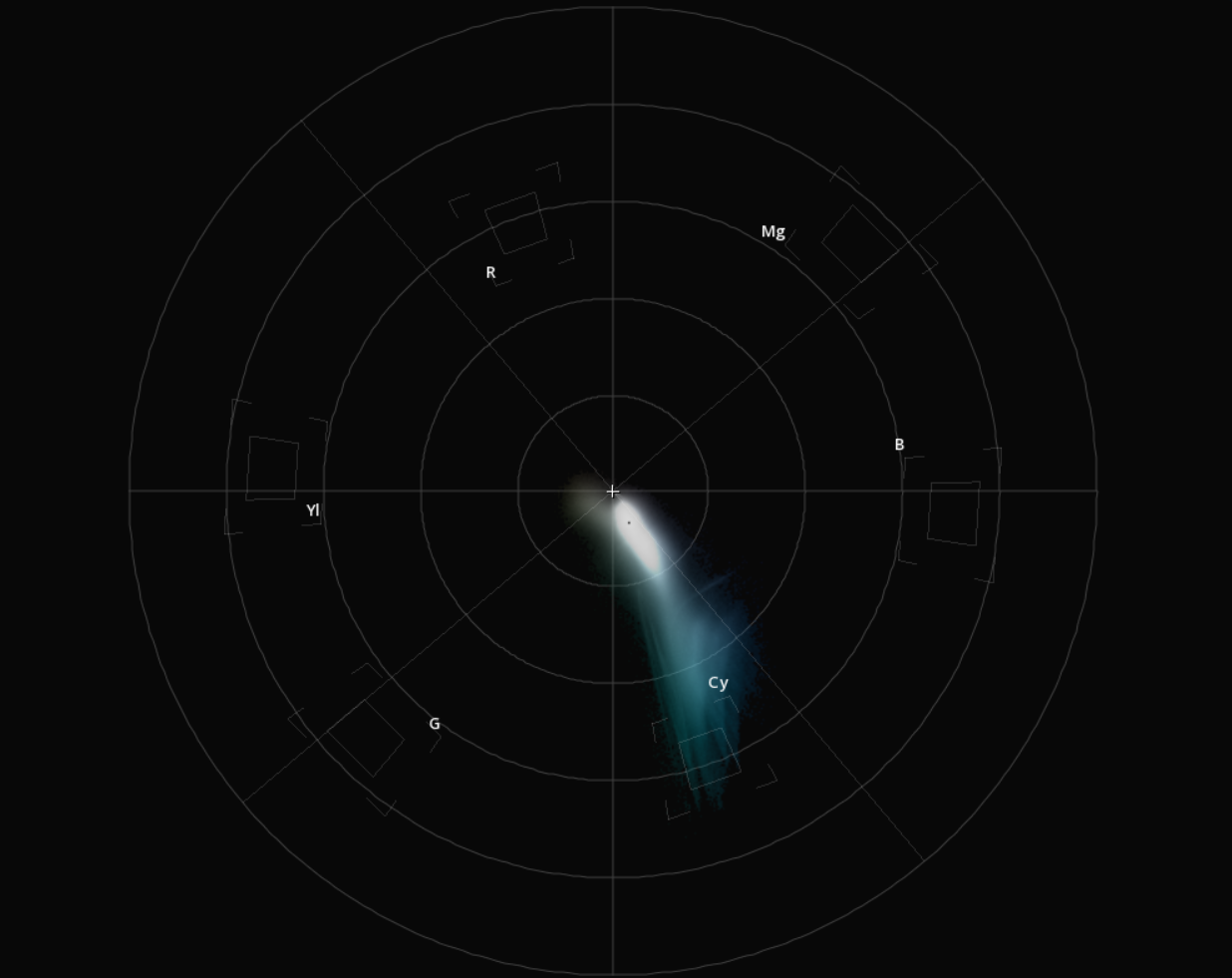
Options
| Labels |
Show/Hide the color labels. |
| Targets |
Showcope-cie.png/Hide the color targets. They represent the maximal values according the Matrix chosen. |
| Sample |
Show the position in the Vectorscope of the pixel at the cursor’s location. |
16.2.3. CIE 1931 Chromaticity Diagram
This diagram allows you to see how the signal is displayed within the color space chosen.
→ You can use Shift+G to display the CIE diagram.
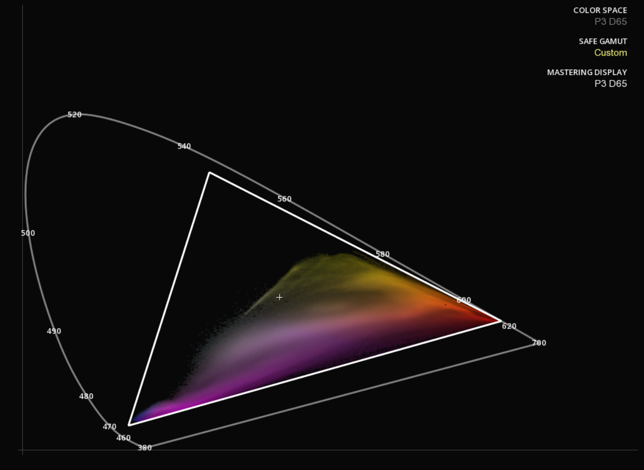
Legend
| Color Space |
Displays the working color space for your content (see Settings | CMS). |
| Safe Gamut |
Display the safe area for a particular color space . (see Settings | CMS) |
| Mastering Display |
Display the capabilities of the Mastering Display . Refer to the Mastering Display section for more information. |
Options
| Sample |
Show the position in the diagram of the pixel at the cursor’s location. |
| Labels |
Show/Hide wavelenghts in nanometers |
| Display |
Show/Hide Mastering Display Information |
| Safe Gamut |
Show/Hide Safe Gamut information |
16.2.4. The Waveform
The Waveform is used to measure and display the level of the brightness, or luminance, of the part of the image being drawn onto a screen at the same point in time.
→ You can use Shift+W to display the Waveform.
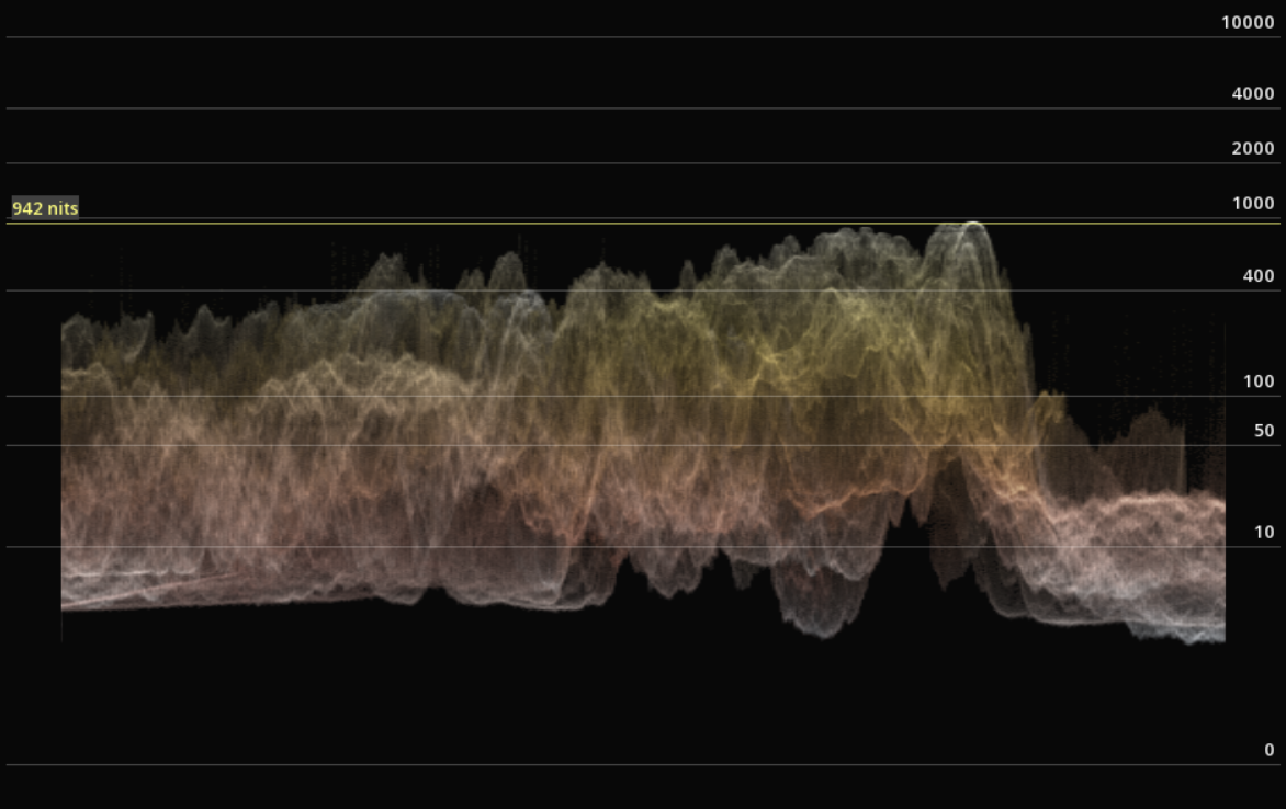
Options
| Type |
You can switch between the traditional video waveform and the ST2084 or HLG modes used for monitoring HDR content. |
| Style |
the Waveform can be set to display information in a large variety of styles. |
| Color Space |
You can choose between the RGB or YCbCr color spaces. |
| Sample |
Move the mouse on the image to show the level at the cursor’s position (yellow line). This value is displayed in percentage in video mode, or in Nits (Candela/sqm) in ST2084 and HLG modes. |
|
When using the type ST2084 the waveform will display the scale in relation to the settings selected for the Mastering Display. |
16.2.5. Zebra patterning
This tool offers different modes in order to inspect the image.
→ to activate the Zebra, use Alt+Z or press Z on the user interface. By default, the Zebra patterning is set on Signal Range mode.
→ to toggle between the different Zebra modes, select them in the Command Panel / Tools / Zebra:

Signal Range
This mode displays in blue the pixels below the boundaries, and in red those above:

|
The Signal range boundaries are defined by the Mastering Display parameters in the Composition Settings. You can also set your own maximal and minimal Luminance values by choosing a Custom Mastering display. |
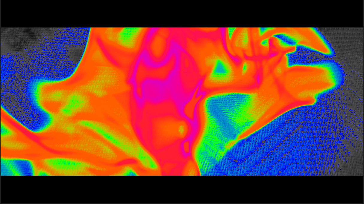
16.2.6. The Luminance Meter
The Luminance meter is used to measure the photometric brightness of an HDR image. It measures the amount of light that strikes a surface in the picture.
→ You can use Shift+N to display the Luminance meter.

| Max Light Level |
Informs you about the higher light level on the current frame. |
| AVG Light Level |
Informs you about the average light level on the current frame. |
| MaxFALL |
Indicates the highest frame average brightness per frame (entire content). |
| MaxCLL |
Indicates the brightest pixel (entire stream). |
| Sample |
Move the mouse on the image to show the level at the cursor’s position (white line). |
| Live view |
Analyses on the fly the MaxFALL and MaxCLL values of the content while it is playing. You can have different nit scales by selecting the desired one with the drop-down menu. |
| Global view |
Allows you to display the full graph statistics values after the launch of a global analysis. For more details refer to the section HDR. |
16.2.7. Pixel Inspector
You can display detailed color information for a specific area of the image (pixel accuracy).
-
To display or hide the Pixel Inspector, use Shift+K.
|
To display the color values, enlarge enlarge the size of the inspector window. |
The information are displayed per color channel (R, G, B and A).
16.3. Audio Monitoring
There is a full set of Audio monitoring tools for the quality control.
→ You can use Shift+A to display the Audio meter.
Select a Type of meter and the desired scale for the meter:
→ Right-Click on OPTION to toggle the meters.
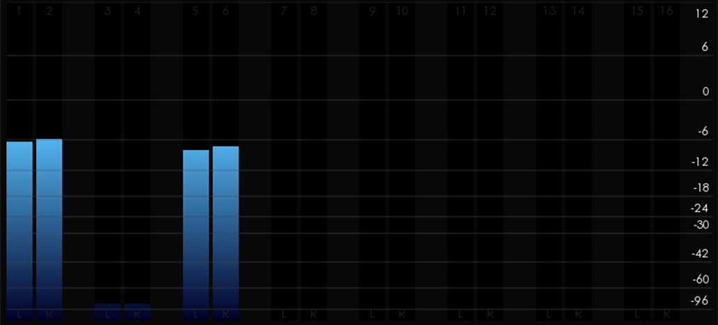
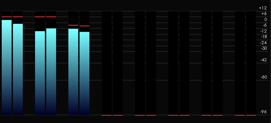
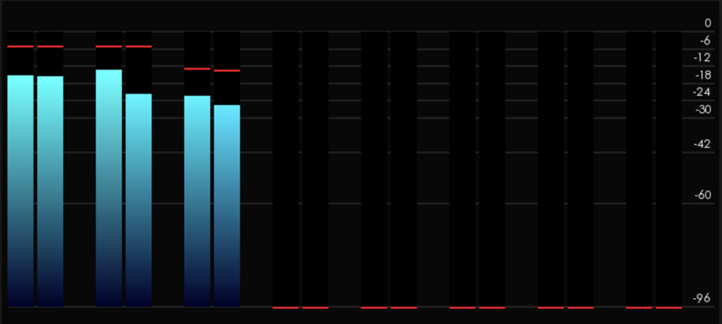
16.3.3. Loudness Meter
The Loudness meter measures the human perceived loudness of an audio content.
Here the Loudness Meter is based on the EBU R128 Loudness recommendation.
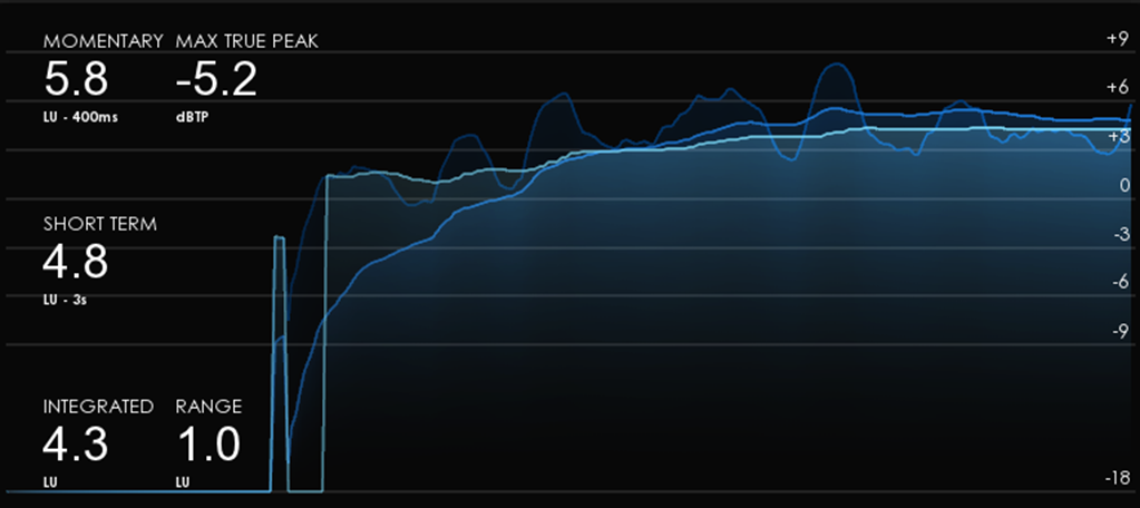
16.3.4. Surround Meter
In this meter, the positions of the full range loudspeakers are marked on a graticule and the amplitude distribution of the sound-field is used to modulate a visual representation, also called "jellyfish display".
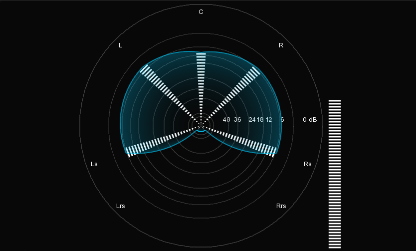
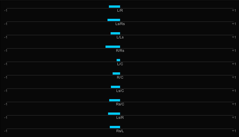
16.4. Peak Signal-to-Noise Ratio
The PSNR computes the peak signal-to-noise ratio, in decibels, between two images. This ratio is often used as a quality measurement between the original and a compressed image. Using the same set of tests images, different image enhancement algorithms can be compared systematically to identify whether a particular algorithm produces better results. The higher the PSNR, the better the quality of the compressed, or reconstructed image.
The PSNR is usually expressed in logarithmic decibel scale. However, you must follow the requirements given by the company asking you a PSNR report. Each company has its own specifications.
16.4.1. Launch a PSNR analysis
→ To launch a PSNR analysis, you need to have the two sources to compare in the Library. The two sources must come from the same content part and have to be of different quality.
→ Open it into the Dual Viewport. For further information, please read the Dual Viewport chapter.
→ Proceed to a Frame Matching and click on LOCK.
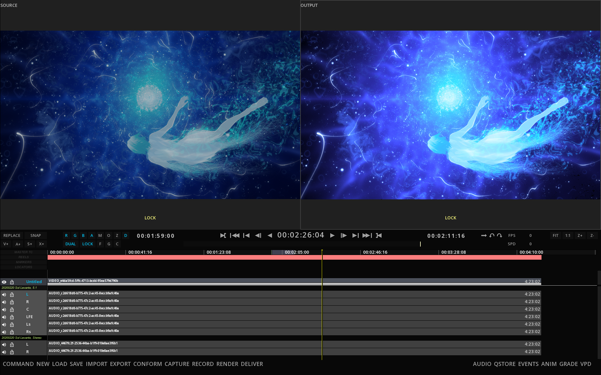
→ Go to the Composition Analysis tool by pressing F6 and select PSNR from the Type drop-down menu.
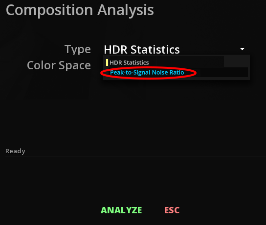
→ Click on ANALYSE to launch the analysis.
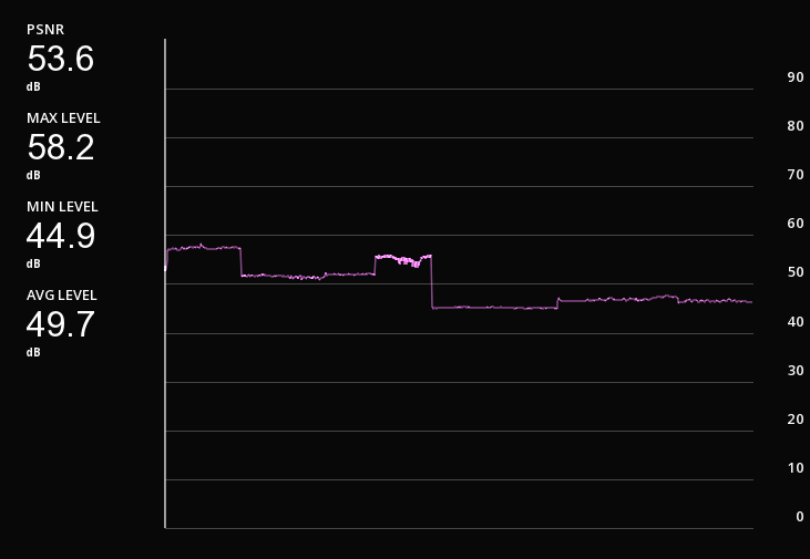
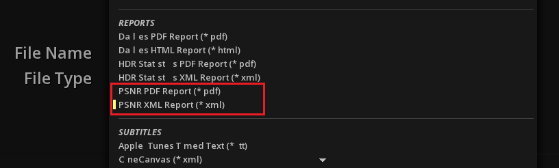
16.5. Bitrate Meter
The Bitrate Meter is used to measure the bitrate of the content playing.
→ You can use Shift+B to display the Bitrate meter.
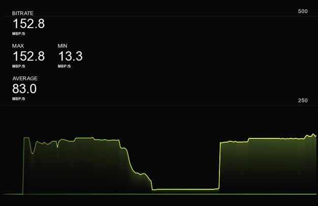
| Bitrate |
Indicates the current bitrate in MBP/s when playing. |
| Max / Min |
Indicates the maximum and minimum bitrate in MPB/s recorded by the meter. |
| Average |
Shows the average analysed bitrate. |
|
the Bitrate meter is active only when you launch the playback. If you stop the playback, the counter will be reset. |
→ You can select the desired scale of reference to read the measures in the drop-down menu.
16.6. Video Pipeline Diagram
The Video Pipeline Diagram allows you to have a quick look at the video pipeline set up.
→ press Alt+F6 to display the diagram:
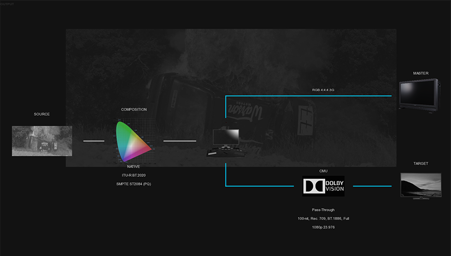
This very useful tool gives you an immediate view of your displays connection settings as well as your color pipeline.
Thanks to a specific color code, you can easyly distinguish the different types of output signals: blue for SDI connexion and cyan for HDMI.
16.7. File based QC Support
Marquise Technologies' solutions integrates with automated file based QC solutions for providing an easier review of the error reports.
Currently we provide support for the following automated QC reports:
-
Aurora (Tektronix)
-
Baton (Interra)
-
Pulsar (Venera)
-
Vidchecker (Telestream)
When loading the XML reports from these automated QC solutions, the operator is able to manually inspect the errors flagged for a media by navigating on the timeline from error to error.
16.7.1. Loading a QC report
You can import a QC report using drag & drop: drop the report in the application window.
→ To navigate from error to error, open the Control Panel / Tools / QC Report:
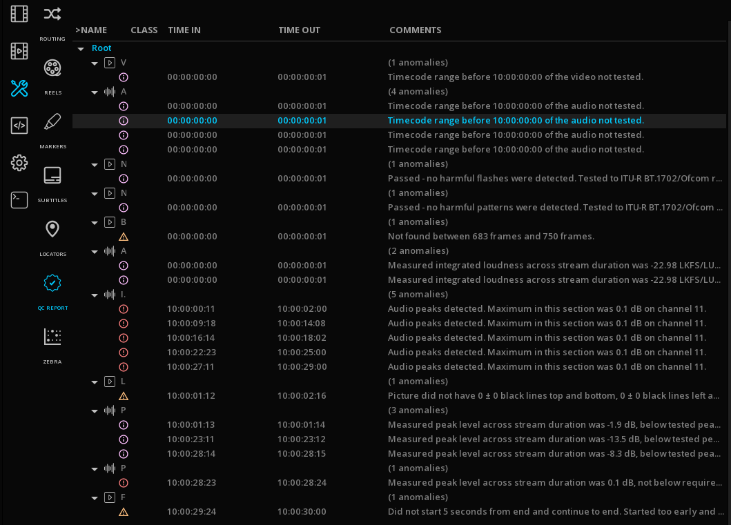
→ Click on a specific Timecode to jump to the location of the error.
→ To display the full error name you can resize horizontally the Command Panel.
17. COLOR CORRECTION
17.1. Overview
This chapter will describe in details the color correction (or color grading) tools available in MIST. The set of color grading tools can be used both for technical purposes as well as for artistic purposes.
In MIST the color correction occurs at the clip level and therefore the tools are available for each video segment available in the timeline. The color correction parameters are completely clip-relative, meaning that each clip carries its own color adjustment values, independently from the others.
The color correction tools are organized in a multi-stage color pipeline, where stages are processed one after each other. While this is true from the logical point of view, the actual computations are handled in a single block to avoid any loss of precision.
17.1.1. Accessing the Grade panel
The first step before you start the grading process is to access the Grade Panel. This can be done either by pressing the corresponding keyboard shortcut kbd:F9] or by clicking on GRADE at the bottom right of the Timeline module.
17.1.2. Using the control surface
MIST supports the Elements Control Surfaces from Tangent Devices.
|
The support for Tangent CP100, Tangent CP200, Tangent Wave and Pandora Evolution models has been discontinued at the end of 2017. No additions or improvements will be made to the models mentioned. However, the disappearance of the support will be done gradually. For any additional questions, contact support@marquise-tech.com |
17.1.3. Grade panel functions
The grade panel comes in several categories:
-
PRIM IN
-
SCC
-
PRIM OUT
-
COMPOSITING
-
DMCVT
Each of these categories divides themselves into several tabs of settings specific to their functions.
However for each of these tabs, you will always have access to the recurring functions, arranged to the right of the Grade panel:
| RESET |
Reset the settings of the relevant tab independently of the others. |
| BYPASS |
Allows you to bypass settings by disabling them. When the bypass is active, the button is highlighted in cyan and the panel is grayed out. Click BYPASS again to make the settings active again. This setting can’t be used for the SOURCE tab for obvious reasons. |
| STORE |
Store the settings of the tab settings in the Quickstore as preset. |
| RECALL |
Recall the settings of a selected preset from the Quickstore. |
| COPY |
Keep the tab settings in memory without saving them as a preset. |
| PASTE |
Apply the settings kept in memory to the active tab without the need to recall a stored preset. |
| AUTO |
This feature automates keyframe creation for each change to the settings. |
| GANG |
When this function is active, any subsequent changes made in the current tab of the Grade panel will be applied to the selected clips. |
| IN |
This setting is only available in the SCC tab. By clicking this button, the selected settings for the affected secondary will be applied to the part of the image inside the shape defined in the * SHAPE * tab. |
| OUT |
This setting is only available in the SCC tab. By clicking this button, the selected settings for the affected secondary will be applied to the part of the image outside the shape defined in the * SHAPE * tab. |
17.2. PRIM IN
17.2.1. Source
Source tab is an essential step in determining the color settings of the clip before starting any color-grading procedure. Especially in the case of RAW files. For more information, please read the chapter Source Settings.
Each clip can be configured individually or together to save time.
-
To modify several clips, start by selecting the desired clips in the timeline.
-
In GRADE / SOURCE, click GANG to the right of the panel before making any changes. This operation is also valid for any other color-grading and Pan & Scan settings.
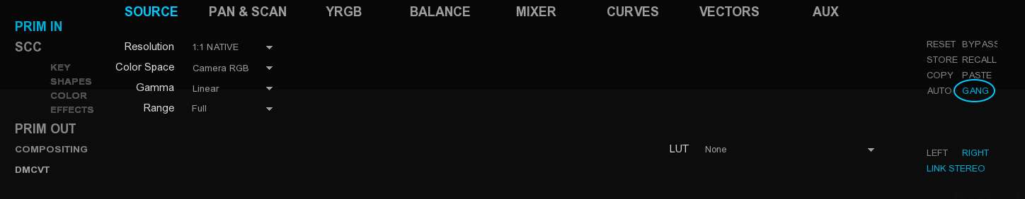
However if you want to reset your settings, you have to be in the desired panel before clicking on the RESET button on the right side of the panel (e.g. if you reset pan & scan, it will not affect the YRGB):
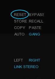
17.2.2. Pan & Scan
Pan and scan is a term used in cinematography to describe geometric adjustments applied on the picture, mostly horizontal and vertical positioning within the frame used for projection/display. Besides frame repositioning, Pan & Scan processes can include zooming in and out of the image and other more sophisticated operations like distortions, etc.
In MIST, the Pan & Scan panel occupies the first position in the color grading pipeline, right after the SOURCE panel.
Reframing the image
Reframing is usually performed when there’s a need to redefine the “center of interest” of an image or readjust the image in the display area.
The most basic use of Pan & Scan tools is for adjusting the position of the picture on the horizontal and/or vertical axis, inside the output frame. These adjustments are performed with the first two parameters available on the left side of the Pan & Scan panel, namely OFS X and OFS Y. These X and Y offsets are expressed in pixels.
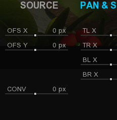
The CONV setting refers to the convergence for Stereo3D content.
The most common case where these two parameters are used, is when the action are, is not perfectly centered on the original media frame. This situation occurs with film scans (when the picture area is slightly shifted to make room for the optical audio track) or when creating a television version of a theatrical release.
The diagram below shows how the picture represented by the light gray area can be positioned within the camera frame (represented by the black frame) by using the horizontal and vertical offset parameters.
The action of positioning the frame horizontally is often called panning, while the vertical positioning is often called racking.
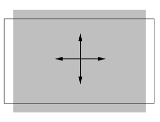
Adjusting aspect ratio
In MIST, the aspect ratio is adjustable per clip. This capability allows even complex projects to be assembled in the same timeline. Nevertheless each of these clips must be adjusted to the desired output frame dimensions and pixel aspect ratio. Several parameters can be used to achieve the same result and it’s important to understand them all in order to select the most appropriate for each case.
Pixel aspect ratio selection
The simplest solution consists of using the dedicated Aspect Ratio parameter. This parameter gives you access to an extensive list of aspect ratios used in the cinematographic industry from 1.00:1 to 4.00:1.
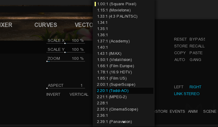
Mirroring
In some cases the original images might be flipped or flopped compared to the correct orientation. Errors or inconsistencies like this might originate in the scanner (inverted scans), in camera (stereo3D, left and right eye views mirrored orientation) or might be the result of a bad transcoding process.
For correcting those errors, you can use the FLIP and/or FLOP commands, found in PAN & SCAN.
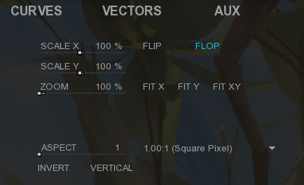
Inverted pictures are not just resulting from technical issues or human errors. It often happens that during the editing phase, a shot gets inverted on purpose. The reason why such a thing could happen, may be a esthetical reason or some other justification that serves the storyline.
Distortion
Image distortion might occur due to a deformation caused by the camera’s lens. It’s usually associated with wide-angle lenses that distort the three-dimensional angle of view by tilting the camera on the vertical axis rather than leveling it to the horizon. This is usually called “keystoning” or the Keystone Effect.
In MIST you can use the PAN & SCAN to independently adjust the four corners of the image relative to the central axis, thus enabling you to compensate for any lens distortion that you might come across.
17.2.3. YRGB
The YRGB tool is the first set of color correction parameters that is used in almost all situations. As a matter of fact, the major corrections always start using this tool and the rest of the toolset is used for refinements.
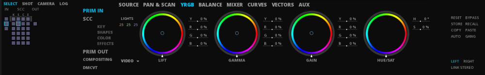
The YRGB tool gets his name from the three letters Y, R, G and B, where R, G and B stand for red, green and blue. The Y letter stands for luminance.
This color correction panel offers three main color wheels that will act on three major parts of color distribution in an image. These parts are essentially the black point, the white point and the distribution of shades between these two points.
Depending on your content and your preferences, you can choose which kind of wheels you want to use with the scroll menu in the bottom left corner:
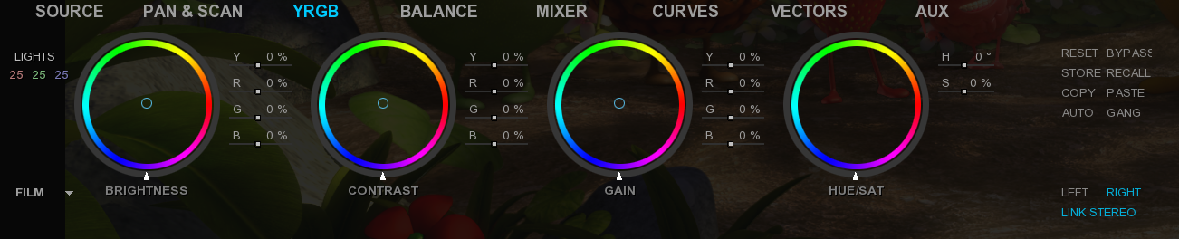
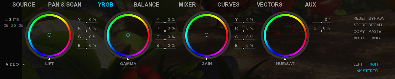
ASC Wheels
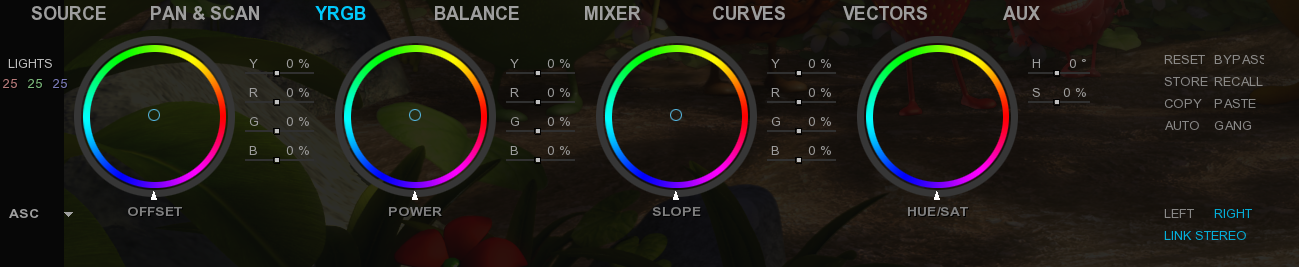
ASC CDL (American Society of Cinematographers Color Decision List) intends to make a translation of the primary colour grading information between any colour correction systems. Therefore, with the usage of ASC-CDL in digital camera workflow, on-set colour correction systems can communicate with any other CDL-compliant colour correction systems on another location. The Director of Photography creates the CDLs during pre-production with the colorist or on-set. Instructions and previews of the primary colour correction are then sent to the colorist, thus allowing an accurate communication.
With Slope and Offset you can produce both a Film Grade “Exposure” and “Contrast” and a Video Grade “Lift” and “Gain”:
-
Offset sets the exposure as well as the lift and the contrast in combination with the slope.
-
Power sets the gamma.
-
Slope sets the contrast with the offset parameters as well as gain and lift.
|
CDL does not define the image state and color management pipeline in which this formula is applied. That means, these ten values describe a color correction but do not describe the way you apply the values. In order to make CDL work, you need an additional Color Management Layer that transforms the image into the correct state, apply the CDL values and eventually convert the image into another image state. Some productions also just create “Lookup Tables” for the input and output transformation and apply the CDL values. |
You can apply your color corrections in several ways:
-
By double-clicking on a value indicated as a percentage, in order to enter new values and validate them with the Enter key.
-
By moving with the mouse, the cursor at the center of each wheel in one direction or another to change the RGB values. To change the Y value, move the white slider on the edge of the wheel in one direction or the other.
-
With a control surface supported by MIST.
|
Remember that you can choose the color wheel orientation display in the user interface preferences in the project settings. |
17.2.4. BALANCE
The color balance is the second tool in the color correction chain and is one of the most used as well. This color correction tool is positioned as second because it is used closely in conjunction with the YRGB tool.
While the YRGB corrections process all the image pixels in the same way, the color balance tool processes them depending on their luminance. In other words, the balance tool will treat differently dark pixels from light pixels from average luminance pixels.
The tool offers separate correction for three luminance-based regions, the SHADOWS, MIDTONES and HIGHLIGHTS. These three luminance regions are present in almost any image and clearly identify dark areas, very luminous areas and the average luminous areas.
In the color balance tool, each of these regions has its own set of selectable parameters that can be adjusted to obtain the desired result. The screenshot below shows the dedicated controls for these three regions:
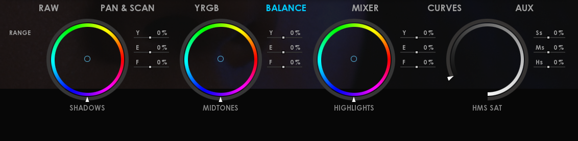
Y |
luminance level |
E |
red-green axe |
F |
yellow-blue axe |
The color balance controls also include for each of the tonal ranges, a saturation control :
Ss |
Shadows saturation |
Ms |
Midtones saturation |
Hs |
Highlights saturation |
The ability to correct independently the shadows, midtones and highlights in an image as well as adjusting the saturation of these regions is extremely important. The YRGB color correction tool described previously may easily introduce color casts in one of these three regions. This is a typical effect during the white balancing process for example.
In order to correct any exaggeration introduced by the YRGB tool, the color balance tool can be used. Among the issues that the YRGB tool can create, one of them is the oversaturation of shadows or highlights. By providing independent saturation control on each of the three tonal ranges, such a problem can be easily corrected.
Like for any others tab, you can bypass them individually by clicking on the bypass button on the right side panel. It allows you to activate or deactivate certain steps of the color pipeline.
17.2.5. MIXER
The Mixer tool allows to send a proportion of one colour channel to another one, in order to drive pixels of a different colour. This is done by taking values from one channel and add them to or subtract them from another.

There are a lot applications for the mixer tool but one could be to obtain a good balance in case where there’s hardly any colour information there to amplify.
Because chances are good that one of the other colour channels has data which you can use by feeding it into another colour channel’s output. This allows you to increase a low-level channel signal without the consequence to increase noise by adding gain.
-
Use the sliders one way or the other to increase or decrease the values.
-
You can also double-click on the value to modify and manually type the one you wish to obtain.
17.2.6. CURVES
The Curves tool allows you to change the gamma as a curve. You can select the desired color channel to modify independently or choose to change all channels at the same time by choosing Master.

Each of them have both input and output components as well as intermediate values points corresponding to a dedicated luminance level. By moving these intermediates points on the graphic, you are changing the gamma.
Unlike other calibration functions that change gamma as a number value, the curves are a more intuitive way to work.
-
To edit a channel, select its color to the right of the graphic. The color of the chart curve changes depending on the selection.
-
Hold the left mouse button on a point to move in the graph.
17.2.7. VECTORS
The Vectors tool allows you to select a certain pixel category defined according to established settings, in order to apply saturation, hue or luminance correction on it.
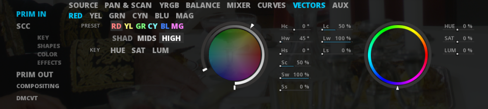
Each color regions is independant and bypassed by default. Click on the BYPASS button to make it active. To select a range of pixels to modify:
-
Select the color region where you need to work on (i.e RED, YEL, GRN etc).
-
Select a color or a tone preset related to the range of pixels you are looking for.
-
You can refine your search by choosing to include search by luminance key (LUM), saturation (SAT) and / or hue (HUE). To do this, click on the concerned settings to activate or deactivate them. Active settings are highlighted in cyan.
-
Use the sliders of the Hue (Hc, Hw and Hs), Saturation (Sc, Sw, Ss) and Luminance (Lc, Lw and Ls) settings to finalize your pixel selection.
|
To see the selected range of pixels in the Viewport, activate the matte layer (M) from the transport bar. 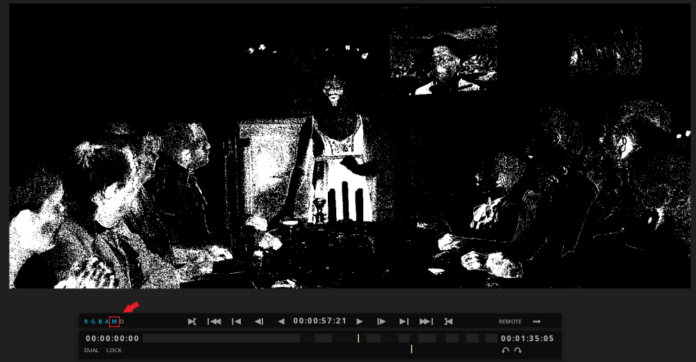
|
-
Once your selection is made, you can move the sliders to the right of the panel, in order to increase or decrease the percentage of HUE, SAT and LUM.
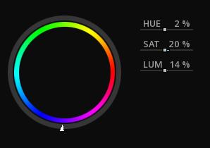
17.2.8. AUX
The AUX tab allows you to apply one or more plug-ins per clip.
For more information on plug-in features and settings, please refer to manufacturer’s documentation.
|
The use of these plug-ins is restricted to specific licensing. For more information, you can write to support@marquise-tech.com |
17.3. SCC
17.3.1. KEY
The Key tool (or matte key) allows you to select a certain pixel category defined according to established settings then apply color corrections on it.
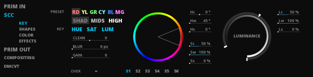
The setting is bypassed by default. Click on the BYPASS button to make it active. To select a range of pixels to modify:
-
Select a color or a tone preset related to the range of pixels you are looking for.
-
You can refine your search by choosing to include search by luminance key (LUM), saturation (SAT) and / or hue (HUE). To do this, click on the concerned settings to activate or deactivate them. Active settings are highlighted in cyan.
-
In order to get a cleaned selection, you can use the CLEAN, BLUR and GAIN sliders.
-
Use the sliders of the Hue (Hc, Hw and Hs), Saturation (Sc, Sw, Ss) and Luminance (Lc, Lw and Ls) settings to finalize your pixel selection.
|
To see the selected range of pixels in the Viewport, activate the matte layer (M) from the transport bar.
|
You can use one key selection per secondary. To switch to another secondary, click on S1 or S2 etc.
Once your selection is made, you can move to the COLOR and EFFECTS tabs or you can move to the SHAPES one in order to define an action area for this selection.
17.3.2. SHAPES
It is possible to create several shapes by secondary. Also, a selection using a Key can be done right upstream.
Basic shape
To create a basic shape, click on the desired one from the list on the left of the panel:
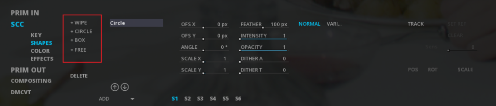
Use the sliders on the right of the panel to change the shape: scale, angle, offset, feather etc.
-
To move a basic shape, hold the left mouse button on the three-dimensional axis of the shape and move there to the desired location in the Viewport.
-
To delete the shape, you must select the shape to delete then click on the DELETE button at the lower left corner of the panel.
Custom shape
To create a custom shape, do the following:
-
Click on FREE from the list of shapes (FREE is highlighted in white until you create the first point of the shape).
-
Left-click on the viewport to place the first point of the shape. Then draw your shape as needed. As soon as the first point has been placed, the shape appears into the list of shape as "Bezier".
-
Press right-click with the mouse on the viewport to close the shape.
You can move the anchor points of your closed shape by keeping the left mouse button on it and drag it into the image in the desired location.
If you want to change the shape of your anchor point, you must hold CTRL + left mouse click on the anchor point to edit and drag your mouse cursor in one direction or the other depending on the effect desired:
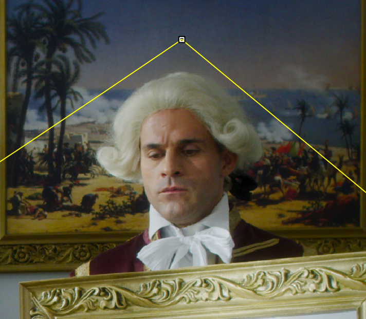
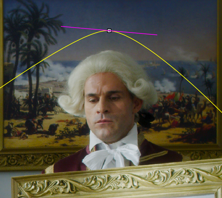
The custom shape is working like the basics ones. You can move and adjust its settings with sliders and delete it in the same way.
Legend of shape path:
| Yellow line |
path line of a finished shape. |
| Red line |
path line of a shape in editing. |
| Blue dashed line |
path of a positive feather value. |
| Green dashed line |
path of negative feather value. |
|
To show or hide the geometry display of the shape, you can use the Alt+G shortcut. |
17.3.3. COLOR
The color corrections applied here refer to the settings explained previously in the chapter YRGB and BALANCE. Please refer to it for more information.
In the same way as the other tabs referring to the secondary ones, each setting is related to a specific secondary. It is possible to have up to six secondary. Each new secondary coming to apply above the previous one. To switch between secondaries, click on the dedicated one ( e.g S3 or S2 etc).
17.4. PRIM OUT
The way to use the PRIMARY OUT tools is very similar to the PRIMARY IN ones. The point is that, these potential modifications are applied after the whole previous layers corrections (i.e primary in, secondaries etc).
For obvious reasons, some settings like SOURCE are missing.
17.5. COMPOSITING
The settings from the COMPOSITING tab allow you to change the composition mode of your clip to others on other video tracks.

-
Select a blending mode from the dedicated drop-down menu.
-
Set the opacity of the clip, using the slider or manually entering the value (double-click on the existing value).
As a reminder, the display of the clip on the video track changes according to the selected compositing mode.
17.6. DMCVT
The DMCVT tab is related to the use of dynamic HDR technology. By default, the panel is empty.
For more information, see chapter HIGH DYNAMIC RANGE.
17.6.1. QuickStore
Accessing the QuickStore
The QuickStore can be accessed by several means. As it is intended to be an in-context view of the grade library, it is possible to show and hide QuickStore directly from the user interface by using the QSTORE button in the lower right part of the screen :
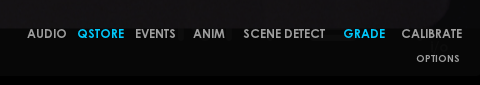
You can click on the QSTORE button to reveal the QuickStore display and click again on the same button for hiding it. When the QuickStore is displayed, the QSTORE button turns light blue. Below is a screenshot of the QuickStore as it appears in the Timeline module, at the very bottom of the screen :
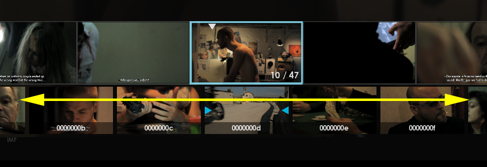
The yellow double-headed arrow shows the extent of the QuickStore as displayed under the Event Viewer (if visible). You can also use the keyboard by pressing the Q key. Pressing the Q key will toggle the visibility of the QuickStore.
Navigating across presets
When the QuickStore is visible, the thumbnails for the presets are displayed horizontally with the current preset being always centered. There is always a current preset, unless the grade library is empty.
When the grade library grows and the number of presets is larger than what can be displayed on screen, then you may need to move the presets around in order to find the one you are looking for:
-
Hold the Alt key pressed on the keyboard.
-
Click on a thumbnail.
-
Drag the mouse to the right or to the left.
The presets will then move accordingly.

When moving the presets around, there will always be one of them in the center. Basically moving the presets to the left or to the right will change the current preset as well.
Direct preset operations
The QuickStore offers also a small set of operations that can be performed directly from the displayed thumbnails. These operations are the most common ones and they are made available from the main grading interface to avoid you wasting precious time.
These functions can be accessed by right clicking with the mouse on the desired thumbnail representing a preset. When doing so, a contextual menu appears as shown in the screenshot below :
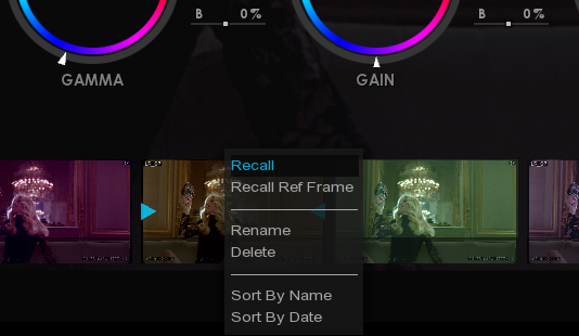
The functions offered by the contextual menu are explained in the following table:
| Recall |
Selecting this option performs a recall of the parameters stored within this preset. All the values of the grade parameters of the shot are replaced with those stored in the preset. |
| Recall Ref Frame |
By selecting this option, the reference frame stored within the preset is loaded in the comparator. This option does not modify in any way the current color grading parameters of the current shot. |
| Rename |
This option allows you to rename the already stored preset. You will be prompted with a request to set the new name. |
| Delete |
When selecting this option, the preset you right-clicked on will be immediately deleted. Once a preset is deleted, there is no way to recover it. Be caution when using this feature! |
| Sort By Name |
By selecting this option, the available presets get sorted by their name. |
| Sort By Date |
This option performs a sorting operation similar to the name sorting described above, but uses the date and time of creation of the present instead of the name. |
17.6.2. Comparing grades
In order to ensure the quality and consistency of color grading, color correction on shots must often be compared with each other.
To facilitate all these operations, MIST has a built-in frame comparator with various visual configurations. The comparator is always working with the current frame in your composition and a dedicated frame store, called the StillStore.
The StillStore is essentially a dedicated memory to store a reference frame. That reference frame can be a snapshot of one of the frames of your composition, a reference frame reloaded from the Grade Library or possibly a still frame you have loaded in the Library on purpose.
Accessing the frame comparator
The frame comparator can be accessed at any time during the grading process.
To activate the frame comparator by using the keyboard, you must press the 8key. Please keep in mind that this key is not the one located in the numerical pad section of your keyboard!
To exit the frame comparator, you must press Alt+8 on the keyboard.
You can also call the Viewport Hot box by pressing Alt + right mouse click and then go to the Comparator tab, to choose Show/Hide the comparator. From this window, you can easily choose to store the current or the original image and define the orientation of the comparator.
Once you have enabled the frame comparator, the frame viewer will be split in two parts. One part will be continuing to display the current frame of your composition, while the other part will be displaying the frame stored in the StillStore.
|
By default the StillStore is empty every time you start a new session or reload a project. As a result the part of the frame viewer where the frame in the StillStore should be displayed is filled up with black. |
17.7. The Storyboard
The MIST Storyboard Panel is a powerful tool that displays all the clip events present in the current composition timeline. It allows the user to create clip groups based on visual appearance characteristics in order to apply the same corrections to all the clips in a group from the many processes available in the Grade module in a single step.
Each clip event that is created in the timeline is automatically displayed as a thumbnail within the Storyboard Panel complete with its own user-definable reference still frame, the name of the original media of the clip, its start timecode and the group number that it may belong to. There is a mini viewport of the current content of the timeline’s playback cursor as well as 32 clip group buttons and selection/grouping tools.
You may also use the Storyboard Panel to quickly copy corrections from one clip to another without having to use an intermediary Grade Library or Qstore grade preset.
17.7.1. Overview
To display or hide the Storyboard Panel open the TimeLine Module (timeline) and press F7 key. Certain controller panels also have a softkey mapped for direct access from the TimeLine Module.
17.7.2. The Storyboard Panel Clip Event Thumbnails
The entire upper portion of the Storyboard Panel is used to display the Clip Event Thumbnails.
Each new video clip placed in the timeline from the Library or created as a result of an editing process (i.e.: Automatic Scene Detection, Razor, Extract, Cutting, Pasting, Lifting a segment that creates a new segment, etc.) will also automatically create a new clip event thumbnail in the Storyboard Panel.
Each Clip Event displays a thumbnail of its reference frame. By default this reference frame is the first frame of the clip at the moment it was created. However it is automatically updated when a processing correction is committed to the clip in the Grade Module by confirming that process with the Confirm Grade function or with the DO button on your dedicated control panel). Each clip also displays information concerning the clip itself in the corners of the thumbnail.
| Upper right corner |
The in-point timecode of the clip in the timeline. If the clip is moved in the timeline, this timecode is automatically updated as well as the thumbnail’s position in the Storyboard Panel |
| Lower left corner |
The name of the source media of the clip is displayed here (without the file type suffix i.e. .mxf, .dpx, etc.). |
| Lower right corner |
The group number of the clips as created in the Storyboard Panel. There are currently 32 groups available per composition. You may join as many clips as you need to a single group |
You may zoom the size of the clips displayed in the Storyboard Panel larger or smaller by holding the Ctrl key then pressing - or +.
In order to be able to see clips in the Storyboard Panel that exceed the size of the screen hold, you may scroll vertically with the mouse wheel.
It is worth noting that these clip events are, in essence, the same clip event that are displayed horizontally in the Event Viewer from the Timeline Module.
When the playback cursor is located over a grouped clip event in the Timeline module, that event is selected in the Event Viewer.
A white triangle is displayed within it and a blue highlight box is displayed around it. All other visible clip events that belong to the same group as the selected clip are highlighted with an orange box around them. This shows which clips will be processed along with the selected clip.
Although you may temporarily select multiple clips to be processed together directly from within the Event Viewer (by holding Ctrl and clicking on clips) the best way to avoid repetitive processes (like applying a single color correction to large series of dallies) is to first group all the clips you wish to process together in the Storyboard and then return to the Event Viewer to apply your corrections to them all.
-
Select a group-affiliated clip you want to modify.
-
Click on the GANG button BEFORE any modifications.
-
Apply your corrections.
Thus, these will be applied to the entire group of the selected clip.
You may also wish to exclude one or more clips from a group temporarily without having to remove them from the Storyboard groups by using Ctrl + click on the grouped clips in the Event Viewer that you wish to exclude.
17.7.3. The Mini Viewport of the Storyboard Panel
In the bottom left corner of the Storyboard Panel is a miniature viewport display of the current play cursor position of the timeline.
The mini viewport is present as a reminder of what the overall aspect of the current clip is so that you may use the Grade Preset copy shortcut function successfully within the Storyboard Panel. The Grade Preset copy shortcut is explained below in the next section.
17.7.4. The Group and Select buttons
In the bottom right corner of the Storyboard Panel are the Group and Select buttons.
The Group buttons are numbered from 01 to 32 and allow you to assign as many ungrouped clips to a single group number as desired.
In order to add clips those are present in the timeline to a Storyboard group :
-
Open the Storyboard Panel F7 from the TimeLine Module.
-
Click on the group number that you wish to assign your clips to (it will be highlighted in blue).
-
Hold down the Ctrl key and left-click on the clips you wish to add or remove from the currently active group.
-
Click on the GROUP button. The grouped clips will display their group number in the bottom right side of their thumbnails. They are also automatically deselected and appear with an orange highlight around them.
In order to ungroup all clips in a single group:
-
Open the Storyboard.
-
Click on the group number you wish to ungroup. The grouped clips appear with an orange highlight around them to show which clips are in the group.
-
Click on SELECT GROUP to select all the clips in the group at once or you may alternatively use Ctrl + click on each clip to manually change its status from deselected to selected. Only clips that are selected will be added or removed from a group. In this way you may choose to ungroup certain clips while keeping others in the group.
-
Click on the UNGROUP button. You may now reuse the group number for a new set of clips to be grouped.
17.8. Stereoscopic 3D Grading
You can use all the grading tools available in MIST to adjust a stereoscopic sequence. In addition you can choose to grade only the LEFT or RIGHT eye images separately or in Link Stereo mode.
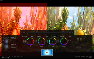
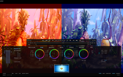
You can easily switch between LEFT and RIGHT eye views to apply different grades on each image. Just select the desired eye before applying a new grade.
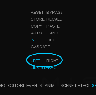
Using the LINK STEREO mode, the grade will be applied to both eye views:
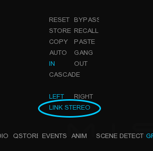
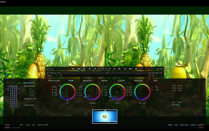
18. HDR WORKFLOWS
18.1. Working in HDR
Marquise Technologies' products allows to work with content in HDR according to a large variety of standards, including:
-
HDR10
-
HLG
-
Dolby Vision
It is possible to playback and inspect HDR10 and HLG content with a variety of tools.
18.1.1. Setting your HDR workflow
To start working in HDR, you need first to define the correct workflow in the .
According to the CMS System chosen, Native or MTCMS, more operations will be available.
When a HDR content is opened in the Timeline, and recognized as is based on the file’s metadata, an HDR logo (HDR10, HLG or Dolby Vision) will be displayed on the top left of the Viewport:
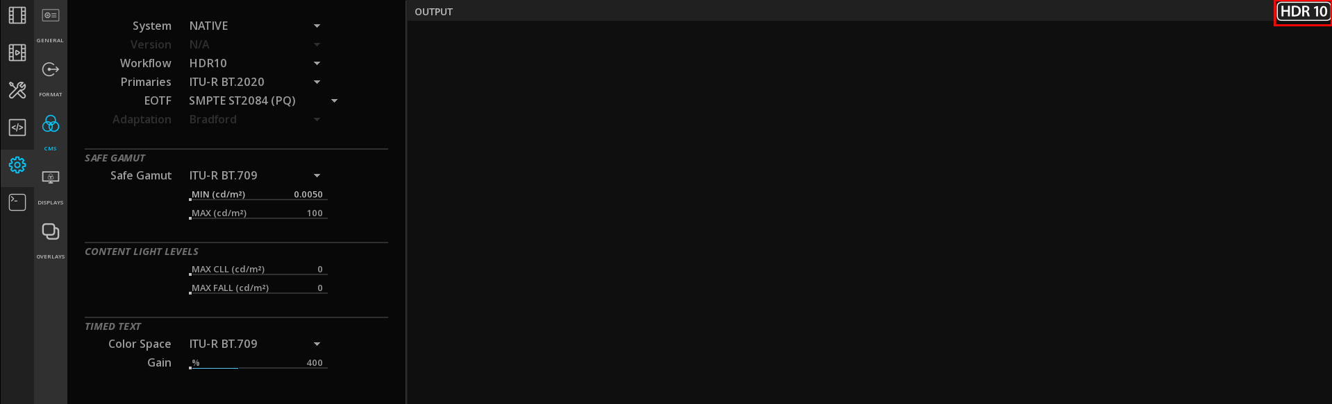
This logo will also be updated according to the CMS Workflow chosen.
For more information about the CMS, refers to Color Management.
18.1.2. Content light levels
When the metadata of the Max FALL and Max CLL are present in the media, they are displayed in the CMS page.
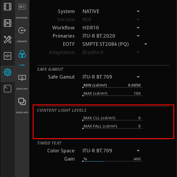
However, these metadata can be wrong or missing.
If you have the information, then you can edit them:
→ Double click on the Max FALL or Max CLL value to modify it and validate with ENTER.
You can also perform a HDR Global Analysis for calculating these values.
18.1.3. Subtitles Color Management
It is possible to manage the subtitle’s luminance independently from the one of the video track.
This is managed in the CMS page under Timed Text Color Space:
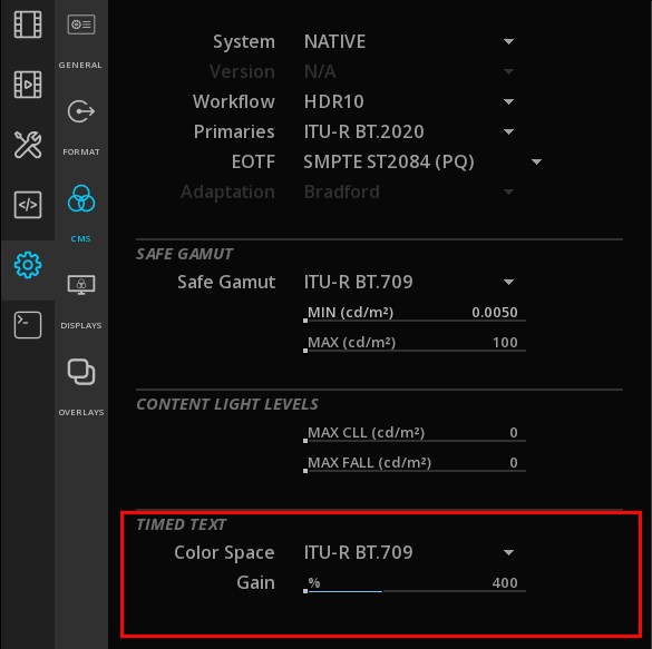
By default, a factor of 4 is applied as gain (e.g. a 100 nits subtitle will appear at 400 nits.), but it can be modified using the Timed Text Gain’s slider.
18.2. HDR Global Analysis
The HDR global analysis tool measures the light level of the composition range defined by the user to obtain the MaxFALL and the MaxCLL values.
The MaxFALL/MaxCLL information is mandatory for some deliverables, especially for HDR10.
Maximum Frame Average Light Level is a metadata recording the average brightness of every pixel in the brightest frame of a given program.
Maximum Content Light Level is a metadata recording the nit level of the brightest pixel in the frame.
Used among others in ST-2086, these values are important in order to control and display the images viewed on the display with accuracy.
Setup the Active Image Area
Before the launch of the analysis, you need to define the aspect ratio of the content to exclude any blanking area from the analysis which could skew the results.
→ , in the Active Area section select the right frame Aspect ratio to define the active area of the image.
→ To see the active image area on the Viewport, press Alt+B to display a green border frame :
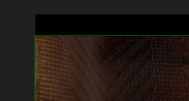
Launch of the analysis
Once the frame aspect ratio has been setup in order to have the appropriate active image area for your content, you can launch the analysis.
→ Go to the Composition Analysis by pressing the F6 key and select HDR Statistics with the Type drop-down menu:
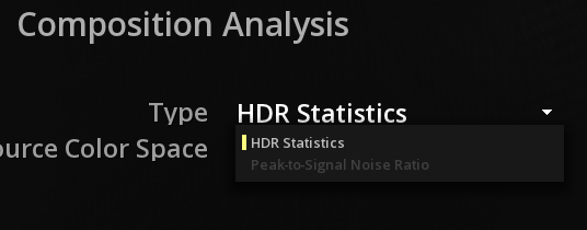
→ Select the Source Color Space corresponding to the content and launch the analysis by clicking on the Analyze button:
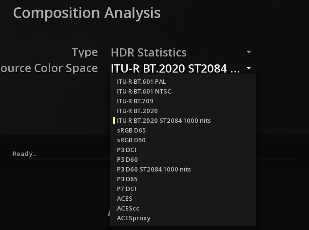
View analysis results
As soon as the analysis has been completed, you can access the results of the analysis by revealing the Luminance Meter with the shortcut Shift+N.
→ Choose the Global type with the drop-down menu to display the full graph of the analysis:
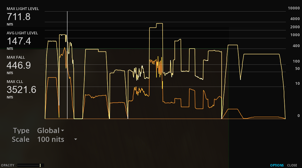
The first values displayed at the top left are the MaxFALL and MaxCLL values of the current image displayed on the Viewport. The values below concern all the analyzed content.
The Content Light Levels are reported automatically after an analysis into the Composition Settings in the CMS page:

|
The Content Light Levels displayed in the CMS tab of the Composition Settings are updated after a new analysis. |
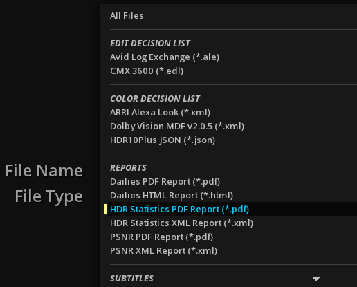
18.3. Dolby Vision
Dolby VisionTM is a proprietary HDR technology developed by Dolby Laboratories, Inc using the PQ curve on the operating principle of Parametric Tone Mapping.
See section Third-party Licenses of this manual regarding all obligations related to the use of DolbyTM technologies.
18.3.1. Dolby Vision Content Mapping and Metadata versions
Marquise Technologies' solutions support the different versions of Dolby Vision’s algorithms: the Dolby Vision Content Mapping version 2.9 (CMv2.9), the Dolby Vision Content Mapping version 4.0 (CMv4) (beta).
These algorithms are linked with different versions of Dolby Vision Metadata:
-
Metadata 2.0.5 (used by CMv2.9)
-
Metadata 4.0.2 (used by CMv4)
-
Metadata 5.1.0 (used by CMv4)
|
Users should select Metadata 2.0.5 for new projects unless otherwise stated from the studio during the transition phase to CMv4 ecosystem adoption. |
|
Projects started or created in one version cannot be converted to another version. |
18.3.2. Content Mapping Unit (CMU)
The Dolby Vision Content Mapping Unit (CMU) is able to emulate a number of secondary display targets and aims to produce images adapted to those displays. It maps the content with the metadata for a specific display, could it be at a standard brightness (e.g. SDR 100 nits) or higher.
The Dolby Vision PQ images as well as the color volume transform metadata are sent to the CMU which "renders" the images before they are outputted to a connected display device.
Marquise Technologies' solutions support the eCMU (external CMU), as well as the iCMU (internal CMU). Both requires a valid end-user Dolby Vision license provided by Dolby Laboratories.
|
The preview of Dolby Vision content can be achieved with 3 methods: - The use of a eCMU device on a non Dolby Vision display device - The use of the iCMU for outputting the image on a non Dolby Vision display device - The tunneling method, for the display on a Dolby Vision display device. In this last case, the CMU is integrated in the device. |
Setup of the eCMU
The Dolby Vision metadata are sent over the SDI to the eCMU. An Ethernet connection allows the software to control the eCMU.
The eCMU has to be setup following Dolby Vision CMU user’s manual. The following picture shows a typical case to setup properly the displays:
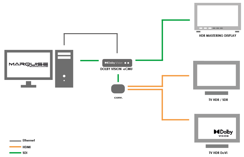
→ To enable the eCMU, select eCMU in the Project Settings, Dolby, Dolby Vision tab.
The good communication between the computer and the eCMU can be verified on the eCMU Home Page by typing its IP address into a web browser:
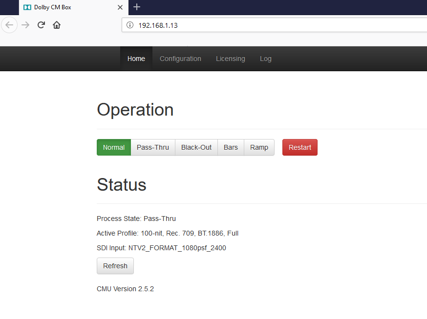
|
Sometimes the Firewall can interfere with the connection between the eCMU and the computer. Remember to configure it accordingly. |
|
The eCMU’s status can also be visualised in the Video Pipeline Diagram by pressing Alt+F6. |
→ Go to the eCMU Home Page to control the eCMU:
→ To perform color corrections, the signal must be set on Normal. If Pass through is selected, the image is displayed without the corrections (bypass).
Setup of the Video Output with the eCMU
In order to display the Dolby Vision technology in an appropriate way, the video output settings into the Project Settings (F1) have to respect some rules:
| Format |
The RGB 4444 format is mandatory |
| Transport |
Choose the SDI level B |
| Scaling |
Scaling must be setup on HEAD |
| Pixel Format |
Select 16 bit |
Setup of the iCMU
See Project Settings / Dolby to install the license for the iCMU.
When using the iCMU, the tone mapping is automatically applied based on the Dolby Vision metadata and the Target chosen before it is sent through the SDI or displayed on the image viewport of the software.

18.3.3. Enabling HDMI Tunneling
The output of Dolby Vision metadata through HDMI is done using the AJA Kona5 video IO card.
→ To allow the sending of the Dolby Vision metadata directly to the consummer TV, the HDMI and the Dolby Vision options must be enabled in the Video Output Settings.
|
The rendering capabilities of the Dolby Vision content is limited by the consummer TV device. For example, not all displays supporting Dolby Vision will read the latest versions of the metadata. |
18.3.4. Setting the Composition for Dolby Vision
The Composition settings need to be carefully chosen for Dolby Vision content.
They are set in .
Select the Versioning mode
It is important to set the Composition in versioning mode to help prevent undesired modifications on the image.
→ Go to and select VERSIONING for the Composition’s type.
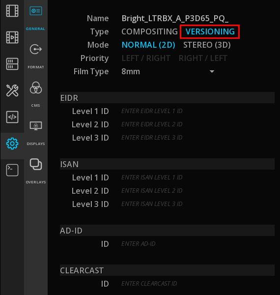
Select the Active Area Aspect
Active image area metadata including the Canvas Aspect Ratio and Aspect Ratio Images information are crucial and mandatory when using Dolby Vision technology.
These metadata are required for knowing the Active Image Area of pixels to be processed. For example, this information is critical in the cases of letter and pillar boxing in order to exclude them from any processing.
→ To select the Active Area, go to and select your aspect ratio from the drop-down menu on your right:
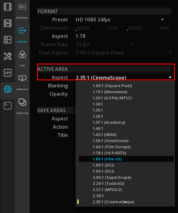
→ To see the active image area on the Viewport, press Alt+B to display a green border frame.
|
If you are importing Dolby Vision metadata, make sure that the Active Area Aspect settings of your composition match those used in the existing Dolby Vision MDF file. |
18.3.5. Setting the CMS for Dolby Vision
→ Whatever the CMS chosen, select Dolby Vision in the Workflow drop-down menu.
→ Select the Primaries. It can be either BT.2020 or P3D65.
→ Select the metadata version in the section Dynamic Tone Mapping:
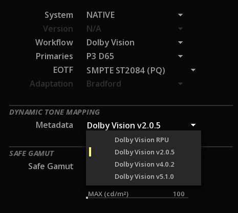
|
Remember that when using MTCMS, it is always necessary to characterize the source color space |
→ Setup the Mastering Display for Dolby Vision in the
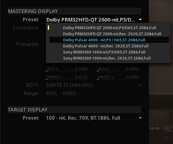
For more information, please refer to the chapter Mastering Display.
|
Set the Mastering Display after having set the CMS properly in order to display the right list of monitors characterization. |
|
If you are importing external Dolby Vision metadata, make sure that the Mastering Display information of the composition match those used in your existing Dolby Vision MDF file (i.e. if Dolby Pulsar is used into the Dolby Vision MDF file, select the Dolby Pulsar from the template list). |
18.3.6. Import of media with embedded Dolby Vision metadata
You can import media with embedded Dolby Vision metadata like any other file.
The metadata will be detected and the CMS settings automatically set accordingly.
In addition, the video track displays a white line representing the embedded metadata.

Displaying the Dolby Vision metadata sections
It is possible to "cut" the video track into sections corresponding to the metadata in order to facilitate the navigation and the QC of the file.
→ Right-click on the video track on the timeline to display the Clip Operations Menu and select Dolby Vision Metadata / Cut:
![DoVi][DoVi](images/49-24.png)
This operation will perform an analysis of the metadata and display the metadata sections as cuts on the video track, easier to navigate from cut to cut or using the Events viewer.
18.3.7. Import of stand alone Dolby Vision metadata
Marquise Technologies' solutions support the two variations of Dolby Vision metadata:
-
Dolby Vision color volume transform metadata into an XML file, aka "Dolby Vision metadata XML file" or "Dolby Vision MDF file".
-
Dolby Vision color volume transform metadata into an ISDX track (MXF file), following the RDD 47 "Interoperable Master Format – Isochronous Stream of XML Data (ISDX) Plugin" specification.
also known as "Dolby Vision metadata MXF file" or "Dolby Vision metadata MXF track"
Import Dolby Vision metadata XML file
There is two methods for importing XML file:
-
Import directly on the clip
-
Import as an auxiliary track
Import on the clip
After the source content is added on the timeline and the composition settings properly set, you can add the corresponding Dolby Vision metadata XML.
→ Right-click on the desired clip on the timeline and choose Dolby Vision Metadata Import:
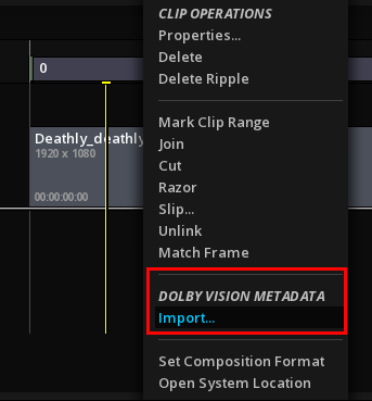
→ Choose the file using the browser and validate with OK.
A successful import will result in displaying a yellow bar on the concerned clip, cut into segments representing the changes in the Dolby Vision’s metadata:
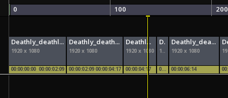
|
The Import Dolby Vision Metadata on clip option is enabled only if the Composition Settings are set on Dolby Vision workflow and the Dynamic Tone Mapping Metadata is Dolby Vision V2.0.5 or higher. |
|
This method works only when the metadata file exactly matches the duration of the clip. |
Import as an Auxiliary track
→ Drag & drop the file in the media bin.
If the XML file is correct, the Dolby Vision logo is displayed in the thumbnail.
To import the XML on the timeline, you must first add a special Auxiliary layer.
→ Press X+ on the timeline and select the corresponding metadata MXF file:

This will add a new layer on the timeline:

You can now place your MDF file at the desired location on the timeline.
Import Dolby Vision metadata MXF track (RDD 57 ISXD)
The RDD 57 ISXD is an MXF file containing the Dolby Vision metadata. This MXF is behaving as any other MXF essence, and is manipulated as a track.
Proceed with the exact same method as described above for importing XML metadata as an Auxiliary track.
18.3.8. Inspecting Dolby Vision metadata
There is different ways to inspect Dolby Vision metadata.
In the the Dolby Vision’s metadata are displayed over two sections:
| STATIC METADATA |
Displays information related to the entire content (Targets, Mastering Display, Color Space, etc.). |
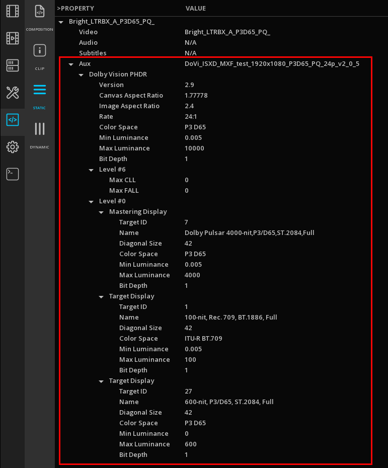
| DYNAMIC METADATA |
Displays dynamic metadata, according to the location of the Playhead. |
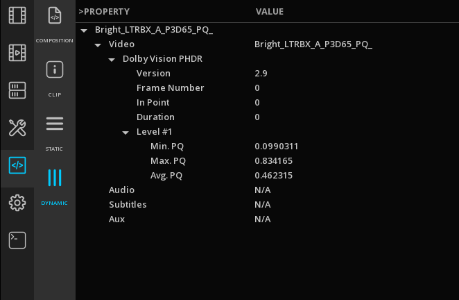
The presence of metadata into the timeline is shown as a color bar on each clip with metadata:

If there is no bar (and the dynamic tone mapping is well selected), it means that your content has no metadata or that the values have been reset.
In a case of overlapped tracks, the METADATA page always display the values of the top track.
If you want to be able to read the lower track metadata, you can hide the top track by clicking to the left of the layer control box:
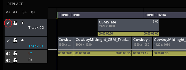
18.3.9. Playback of Dolby Vision content with the CMU
The CMU allows to playback Dolby Vision content with metadata for the different targets present in the Dolby Vision metadata file.
All targets available for a Dolby Vision metadata file are available in :
→ choose a Target from the drop-down menu:
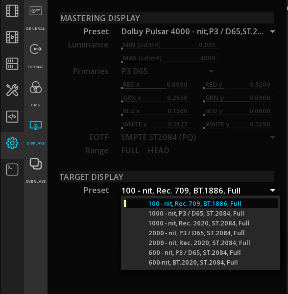
|
Target Displays are available in the DISPLAYS page only if a valid Dolby license is loaded and the CMS workflow is set on Dolby Vision. |
→ You can also activate the dynamic tone mapping display for the viewport:

In this case the iCMU is used to display the final result on the image viewport.
18.3.10. Dual output for Dolby Vision
It is possible to output 2 different streams of Dolby Vision content, with or without tone mapping applied:
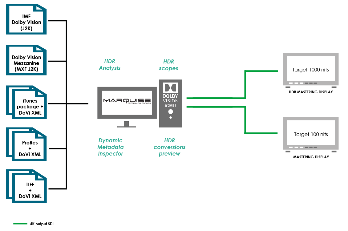
|
Refer also to Dual Video Output for setting up the video output matrix. |
18.3.11. Analyzing clips
Image Characteristics Analysis
The Global Analysis and the Image Characteristics Analysis are two different analyzes. The behavior and the use of the tone mapping are not the same.
It is on the Image Characteristics Analysis made on each clip that the generation of Dolby Vision metadata is based.
The Image Characteristics Analysis is based on the levels of the image and not on the number of pixels of a given value.
Proceed of the analysis
Setting the timeline for an Image Characteristics Analysis of clips is done like for the Global Analysis. Please read the chapter HDR Global Analysis for reference.
→ Select the clip you need to analyse and open the Composition Analysis panel using the F6 key and select HDR Statistics from the drop-down menu.
|
If you don’t select any clip, the Global Analysis will be processed instead. |
|
The clip has to be included within the composition range to be analyzed: |
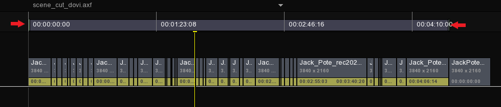
18.3.12. Editing the metadata
Common editing operations also apply in a Dolby Vision workflow. Nevertheless, some small differences in the behavior of metadata are worth noting.
Adjusting the duration of a clip
It is possible to adjust the duration of the clips, in particular to extend a clip duration with the cursor:

Cut a clip
The cuts in Dolby Vision correspond to the change of metadata from one image to another and not from one plan to another. Although Dolby Vision cuts may corroborate with narrative cuts, keep in mind that the reference unit for Dolby Vision is a frame and not a clip.
→ To cut a clip, right-click on the clip into the timeline to access to the Clip operations menu. By clicking on Cut, the clip will be split at the Playhead position:
By cutting a clip with Dolby Vision metadata, the two halves of the clip newly generated after the cut will keep the same metadata. When using the Razor tool, the behavior is the same. Please read the chapter Cutting clips for more information on editing operations.
Join function
The join function is accessible via the Clip operations menu. Place the Playhead on the desired clip to be joined, right-click on the clip and select Join:
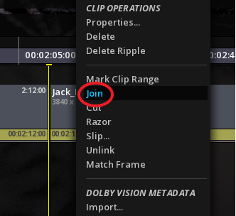
When joining two clips, the metadata of the first clip are applied to the second one.
Working with multiple video tracks
It is possible to work in Dolby Vision with multiple video tracks.
Because the composition is set in VERSIONING mode, the output of the composition will always be flattened.
The two following schemes will help you understanding how the multiple tracks are rendered:
1. The upper track overlays the gap
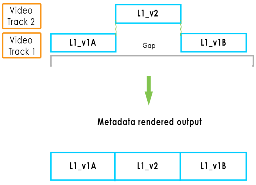
2. The top track overlays a part of the clip from the bottom track
In this case, the Dolby Vision metadata that are taken into account are ALWAYS the one from the top track:
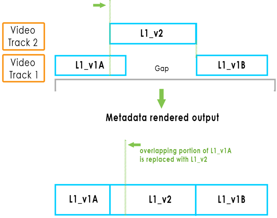
Management of gap
Dolby Vision doesn’t allow any gap in the metadata. When there are gaps between shots on the timeline, you have to fill them with black frames to match the duration of the gap. Once it is done, launch an Image characteristic analysis on it.
Editing of a muxed Dolby Vision file
A muxed Dolby Vision file is an MXF JPEG2000 with the Dolby Vision metadata embedded. This file is being described in a future released SMPTE document, RDD 56 "Track File for JPEG 2000 Codestreams with Time-Synchronous Metadata".
In the timeline, such a file is represented with the metadata colored in white, meaning read-only.
To edit the file, you must first perform a cut:
→ Import your muxed file into the timeline then right-click on the clip in order to access to the Dolby Vision Metadata operations. Click on Cut:
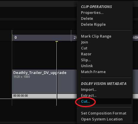
The muxed file is now cut in several clips and the color clip bar has changed from white to yellow, meaning the metadata are now editable.
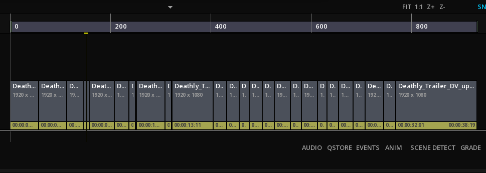
Extract metadata from a muxed Dolby Vision file
To extract the metadata of a muxed Dolby Vision file, follow these steps:
→ Place the file on the timeline and right-click on the clip to access to the Dolby Vision Metadata operations menu. Then click on Extract:
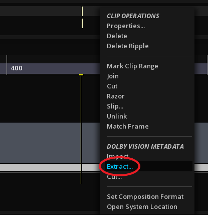
→ In the window Export Dolby Vision Metadata, select a location, name your XML file and select Dolby Vision MDF as File Type.
→ Click on OK to validate.
Exporting a Dolby Vision MDF file
It is possible to export a Dolby Vision MDF file from the timeline.
|
The actual composition range is not taken into account for this operation: all the clips of the timeline will be included in the MDF file. |
→ To export a Dolby Vision MDF file, click the Export button:
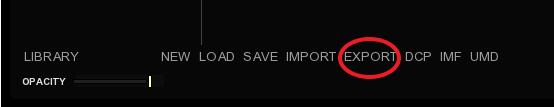
→ When the export window opens, choose the path of the file to export. Then after having named it, select in the File Type drop-down menu the Dolby Vision MDF extension in the category EDIT DECISION LIST:

→ Click on *OK*to export the file.
18.3.13. Export Dolby Vision content
Once the Dolby Vision metadata have been applied to the source file, MIST offers different solutions to package the finalised content.
All the possible exports are created from the Master Delivery panel (button DELIVER in the timeline).
See Master Delivery for detailed information on the Master Delivery Panel.
Export as Dolby Mezzanine
A Dolby Mezzanine file is a muxed Dolby Vision file (aka SMPTE RDD 56) with audio:
-
In the Master Delivery panel choose Dolby Mezzanine in the list of available formats.
Export as IMF Application 2e
MIST allows you to export your Dolby Vision content as an IMF Application 2e package:
-
In the Master Delivery panel choose Interoperable Master Format in the list of available formats.
-
In the GENERAL tab, first select the desired Specification from the drop-down menu:
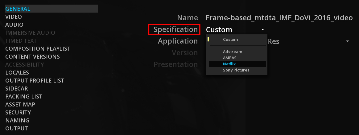
-
then use the drop-down menu for Application and choose ST2067-21 Application #2e Dolby Vision.
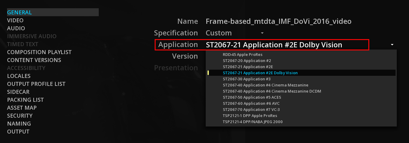
MIST supports the versions 2016 and 2020 of the ST2067-21 standard. Refers to your delivery specification to choose the appropriate one:
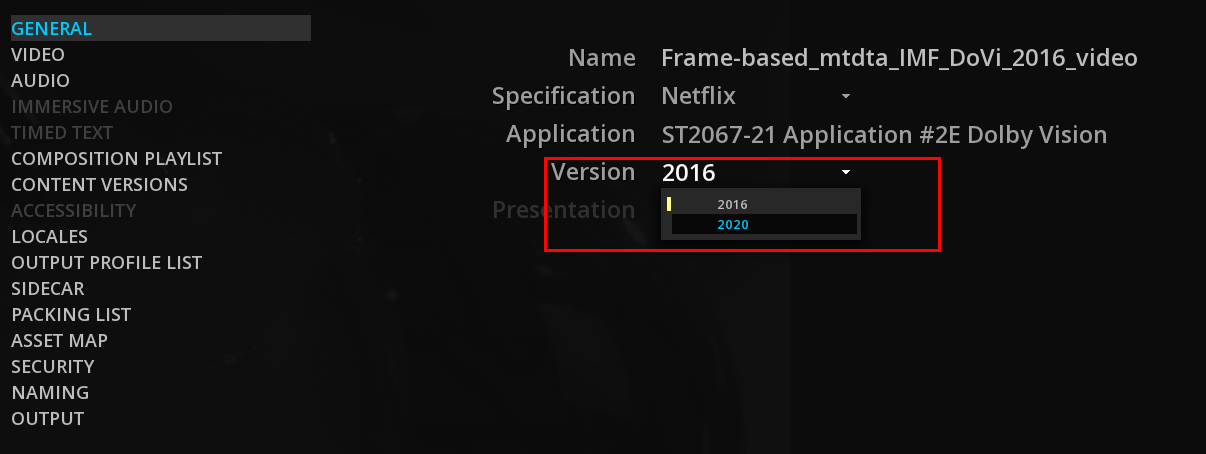
See IMF Mastering for more information on the IMF creation.
Export as Dolby Archival Master
A Dolby Archival Master is composed of image sequences (DPX, TIFF, OpenEXR) with specific colorimetry and the corresponding Dolby Vision metadata, either as MXF or XML file format.
MIST offers the presets for Dolby Archival Master deliveries:
-
In the Master Delivery panel choose Dolby Archival Master in the list of available formats.
-
In the VIDEO tab, select the type (DPX, TIFF, OpenEXR) and its encoding parameters.
Export as an iTunes package
-
To export the content as an iTunes package, go to the Master Delivery panel and choose Apple iTunes Package in the list of available formats.
Refer to Apple iTunes Package for additional information.
18.3.14. Render with tone mapping
MIST is able to create a variety of deliverable using the Dolby Vision tone mapping: it uses the iCMU to create the final look for a particular target, i.e. Rec 709 100 nits and then encode the image into the desired file format.
|
This feature requires the iCMU with a valid Dolby Vision license |
To create a deliverable with the tone mapping applied, first load the timeline with a source content containing the Dolby Vision metadata and display the tone mapping for the Viewport with the button D.
-
In the DELIVER panel, select the desired format
-
In the VIDEO settings, for Dynamic Range choose "Apply Tone Mapping"
|
The following masters cannot be created using tone mapping because they carry the Dolby Vision metadata embedded in the video file: |
18.4. HDR / SDR conversions
MIST allows you to manage color conversions from one color space to another, whether SDR or HDR. Based on the use of the latest standards and recommendations, you can convert your media using either the MTCMS or the ACES system. Here, only the MTCMS system will be explained.
It is impossible to present all possible cases, therefore, only specific cases that need to be detailed will be addressed. We invite you to refer to the chapter Setting the CMS that explains the inner workings of MIST CMS to help you understand which settings would apply to your situation.
|
To learn how to handle color conversions for creating a DCP, please read the chapter Color management for DCP. |
18.4.1. Cross-conversions workflow
The conversion principle works as follows:
-
Set the CMS by choosing the color settings you want to convert to.
-
Select the Mastering Display in relation to your CMS settings. This is to define the relationship between different scales used for conversion (such as PQ and HLG). Mastering display defines the scale to which the conversion must be made. When selecting a mastering display for cross-conversion, select a standardized template such as Std. Rec709 or ITU-R BT.2100. Indeed, some templates associated with monitors (e.g TVLogic LUM-310R or Sony BVM templates) can optimize the display according to the concerned monitor but will not be recommended for the use of a conversion.
-
Properly characterize the source according to the properties of the clip. If you have multiple types of source in your timeline, the process is the same. You need to define all of them according to their properties in order to convert them. For information on how to define the source please refer to Source settings.
Once these operations are completed, the conversion is operational. To cross-convert subtitles, please refer to the Text Luminance gain chapter.
It is important to remember that the color pipeline of MIST works in FULL range. In order to make the conversion correctly, make sure that the selected Range in the SOURCE settings is in compliance with your clip, otherwise the conversion will use wrong levels.
For example, some formats such as the ProRes 4:2:2 HQ uses YUV sampling and therefore involves a range in HEAD. However, the format can not contain this information as metadata. MIST can not detect it to configure your source automatically. Be vigilant so watch out for the range of your clip.
18.4.2. Cross-conversions verification
With the scopes available in MIST, it is possible to ensure the result of the conversion by checking the arrival values of your image in the Viewport.
-
Prior to the verification, check if the selected MASTERING DISPLAY is appropriate to the content displayed and recently converted. In addition to displaying your content in the right conditions, your scope will display the scale of values in consequence (e.g the scope will use 2000 nits as maximum if choosing a mastering display using 2000 nits as its maximum white luminance level).
-
Open the Waveform by pressing Ctrl+W.
-
From the TYPE drop-down menu of the scope, select the one corresponding to your content whether HLG, Video or ST2084 (PQ).
-
With the cursor browse the Viewport to inspect the luminance values. The value read is displayed in yellow in the waveform.
Be aware that there is some tolerance for the accuracy of the rounded values indicated in the scopes.
|
For the same mastered film in two different color formats, it will be impossible from these two different sources to obtain an equivalent conversion (e.g., same content mastered in SDR and PQ will not give the same result when converting to HLG). |
18.4.3. Upscaling SDR to HDR
HDR gain
MIST allows you to control the up-convert process of an SDR signal by setting the desired gain setting for mapping the SDR levels to HDR:
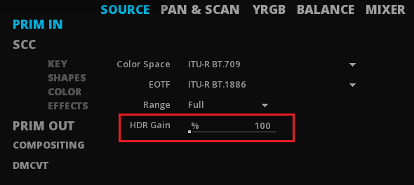
|
The HDR gain setting is enabled only if your source is set to an EOTF SDR and your MTCMS is in HDR. |
-
ITU BT.2390 recommends to apply a gain from 203% to 265%, in order to maintain a "traditional SDR look" for BT.2100 HLG.
-
To achieve consistent mid-tone luminance levels when mapping standard dynamic range content into PQ, it is advised to keep 100% of gain.
|
100% is the default value in MIST, knowing that the percentage expressed corresponds to its equivalency in nits (i.e 100% = 100 nits). |
Nevertheless, these are recommendations and not standards. These values are for information only. Depending on your content and the expected result, it is entirely possible for you to define the percentage yourself.
As specified in BT.2390-4, the gain factor is applied to the source before any image manipulation such as trim pass and grades.
SDR to BT.2100 HLG
-
Choose MTCMS as color system in the CMS tab of COMPOSITION SETTINGS.
-
Select HLG as Workflow: Primaries will be automatically set on BT.2020 and EOTF on BT.2100 HLG.
-
From the DISPLAY tab, select ITU-R BT.2100 HLG 1000 nits.
-
For all the clips in the timeline, you have to characterize the source from the SOURCE tab of the GRADE panel then apply an HDR gain percentage from 203% to 265%.
SDR to ST2084 PQ
-
Choose MTCMS as color system in the CMS tab of COMPOSITION SETTINGS.
-
Select HDR 10 as Workflow: Primaries will be automatically set on BT.2020 and EOTF on ST2084 (PQ)
-
Select BT.2100 PQ 1000 nits as Mastering Display.
-
For all the clips in the timeline, you have to characterize the source from the SOURCE tab of the GRADE panel. You can use the default 100% HDR gain percentage for PQ conversion.
18.4.4. Cross-conversions from PQ
ST2084 PQ to BT.2100 HLG
-
Choose MTCMS as color system in the CMS tab of COMPOSITION SETTINGS.
-
Select HLG as Workflow: Primaries will be automatically set on BT.2020 and EOTF on BT.2100 HLG.
-
From the DISPLAY tab, select ITU-R BT.2100 HLG 1000 nits.
-
For all the clips in the timeline, you have to characterize the source from the SOURCE tab of the GRADE panel. Here, select ST2084 as EOTF and BT.2020 as color space. You don’t need to apply any HDR gain. Keep it at 100%.
ST2084 PQ to SDR
-
Choose MTCMS as color system in the CMS tab of COMPOSITION SETTINGS.
-
Select Custom as Workflow
-
Select BT.709 as Primaries
-
Select BT.1886 as EOTF.
-
Select std. rec709 BT1886 100 nits as Mastering Display.
-
For all the clips in the timeline, you have to characterize the source from the SOURCE tab of the GRADE panel. Here, select ST2084 as EOTF and BT.2020 as color space. You don’t need to apply any HDR gain. Keep it at 100%.
18.4.5. Cross-conversions from HLG
BT.2100 HLG to ST2084 PQ
-
Choose MTCMS as color system in the CMS tab of COMPOSITION SETTINGS.
-
Select HDR 10 as Workflow: Primaries will be automatically set on BT.2020 and EOTF on ST2084 (PQ)
-
Select BT.2100 PQ 1000 nits as Mastering Display.
-
For all the clips in the timeline, you have to characterize the source from the SOURCE tab of the GRADE panel. Here, select BT.2100 HLG as EOTF and BT.2020 as color space. You don’t need to apply any HDR gain. Keep it at 100%.
BT.2100 HLG to SDR
-
Choose MTCMS as color system in the CMS tab of COMPOSITION SETTINGS.
-
Select Custom as Workflow
-
Select BT.709 as Primaries
-
Select BT.1886 as EOTF.
-
Select std. rec709 BT1886 100 nits as mastering display.
-
For all the clips in the timeline, you have to characterize the source from the SOURCE tab of the GRADE panel. Here, select BT.2100 HLG as EOTF and BT.2020 as color space. You don’t need to apply any HDR gain. Keep it at 100%.
19. MASTER DELIVERY
The Master Delivery panel is a dedicated interface allowing the creation of deliverables requiring specific packaging and metadata according to a Delivery Specification in an automated way.
The Master Delivery panel, formerly known as UMD (for Unified Master Delivery), simplifies the creation of a variety of masters with a similar interface whatever the type of delivery chosen.
It also allows to rewrap content when creating versions without re-encoding the image.
19.1. Access the Master Delivery panel
→ You can access to the Master Delivery panel panel by clicking on the DELIVER button on the Menu Bar of the timeline module:
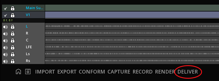
→ Click on the EXIT button to leave the Master Delivery panel.
19.2. Type of Deliverables
The deliverables available in Master Delivery panel are organized in different categories:
-
FORMATS, for formats and packages
-
SPECIFICATION, for a direct access to specific studios or broadcasters delivery specifications
-
CUSTOM, to access the list of saved presets.
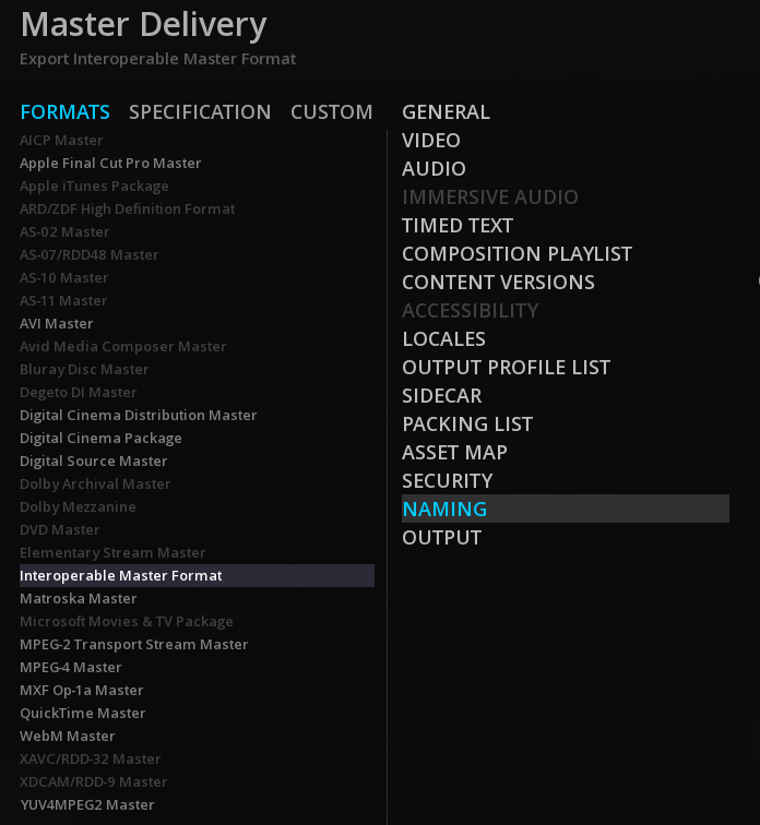
|
The list of available deliverables depend on the composition. If its settings are not compatible with a format, its name is grayed and you cannot select it. |
19.3. Common Deliverable parameters
Once a deliverable is chosen, the second column of the Master Delivery panel displays a number of parameter pages for defining the necessary metadata, video, audio and output information for this format.
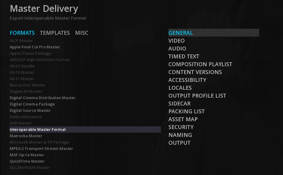
Whatever the deliverable chosen, they have in common a minimum set of parameters: General, Video, Audio, Output.
Other parameters like Immersive Audio, Acessibility or Manifest can be retrieved in several output format as well.
|
A specific parameter will have the same user interface behavior whatever the type of master chosen. Depending on the type of output, different options may be available. |
19.3.1. Navigating trough the parameters pages
Some keyboard shortcuts allows you to quickly navigate through all the parameters pages of a Master, typically when checking the settings before launching the export:
Home |
Go to first parameters page |
End |
Go to last parameters page |
PgUp |
Go to previous parameters page |
PgDn |
Go to next parameters page |
19.3.2. Multiple Tracks Management
By default, MIST will present all the Active assets tracks present on the timeline in the DELIVER pages.
If several audio soundfields, timed text tracks or Immersive Audio are present, they will be all listed in their respective page.
|
All the tracks present in a page will be added in the Delivery in the order they appear in the list. |
You can manage the tracks to be included or not in the delivery using the bottom page icons:
|
Delete |
Remove the selected track from the Delivery |
|
Add |
Add a new track for the Delivery. |
|
Reset |
Reset all manual changes and display all the Active assets tracks present on the timeline |
|
Move Up |
Move up the selected track in the list |
|
Move Down |
Move down the selected track in the list |
Alternatively you can use some keyboard shortcuts:
Delete |
Delete |
Remove the selected track from the Delivery |
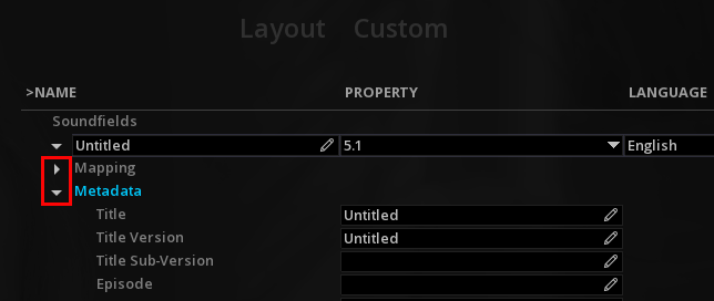
19.3.3. Metadata
All the information set either manually or using a drop down menu will be added in the output file as metadata.
The metadata are Format and Specifications dependant and vary according to the Master chosen.
|
If a metadata is already present in the source track, MIST will automatically display it. |
→ Fill all the required metadata using either the ![]() Edit icon or the drop down menu:
Edit icon or the drop down menu:
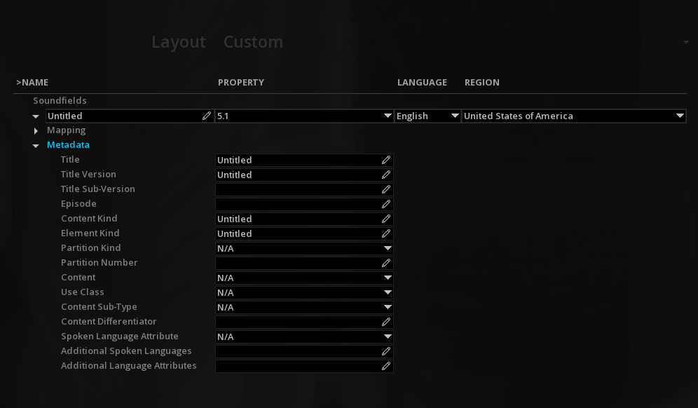
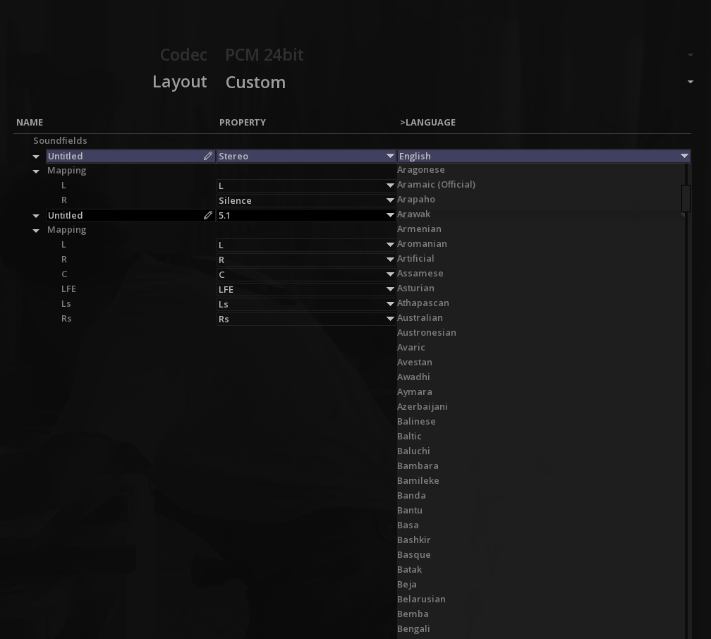
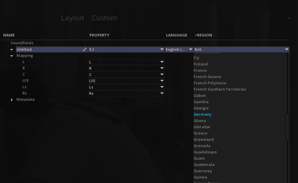
19.3.4. General page
| Name |
This is where you enter the name of the file. MIST will create a directory using this name, unless other wise specified in the Naming page. |
| Specification |
Select a Studio Delivery Specification for this format, or create a Custom one. |
|
The list of available specifications depend on the composition. If its settings are not compatible with an existing Delivery Specification, it will not appear in the drop down menu. |
19.3.5. Video page
In this page you set the parameters for the Video essence. The container, codec, bit depth and chroma subsampling are Specification dependant. MIST automatically constraints the settings according to the chosen shim of the delivery specification.
To display all the parameters available for a format, the Specification must be set to Custom.
|
About Color Space parameter |
19.3.6. Audio page
Like the Video, the Audio essence encoding parameters are constrained according to the chosen shim of the delivery specification.
| Codec |
if the shim allows more than one audio codec, you will be able to select it from the drop down menu. If not, MIST will display in grey (not modifiable) the codec in force for the shim. |
| Layout |
Depending on the Specification, you can have the choice of Custom audio layout or some fixed audio layouts. |
Custom Layout
In custom mode, it is necessary to manually select the audio tracks to be encoded. The reason is that a composition may have multiple audio layouts or soundfields and possibly not all of them are required for a specific output.
Soundfield Name
For each audio layout, MIST displays by default an Untitled soundfield that you can edit:
Layout Configuration
→ To choose or modify the layout configuration, use the Property's drop down menu:
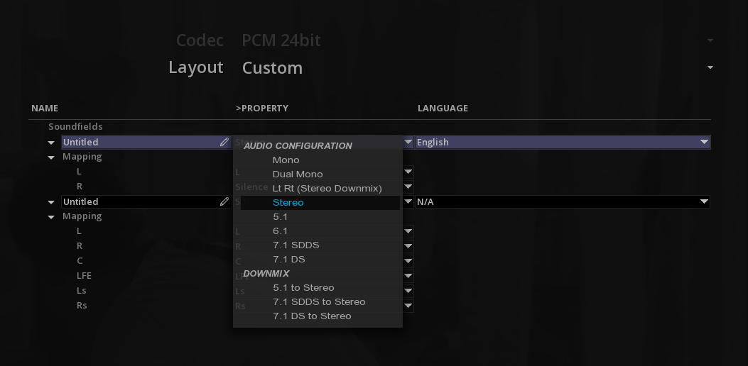
Channel Mapping
→ Use the Channel Mapping drop down menu to manually change the audio tracks distribution:

|
Remapping channels is very useful when a source content is not correctly configured, as you do not need to modify the timeline. However, this remapping concerns the entire track and not the individual audio clips present on the track. See also Audio remapping in the Audio Management chapter. |

19.3.7. Immersive Audio
If an Immersive Audio track is present on the timeline, it will be listed in the IMMERSIVE AUDIO page.
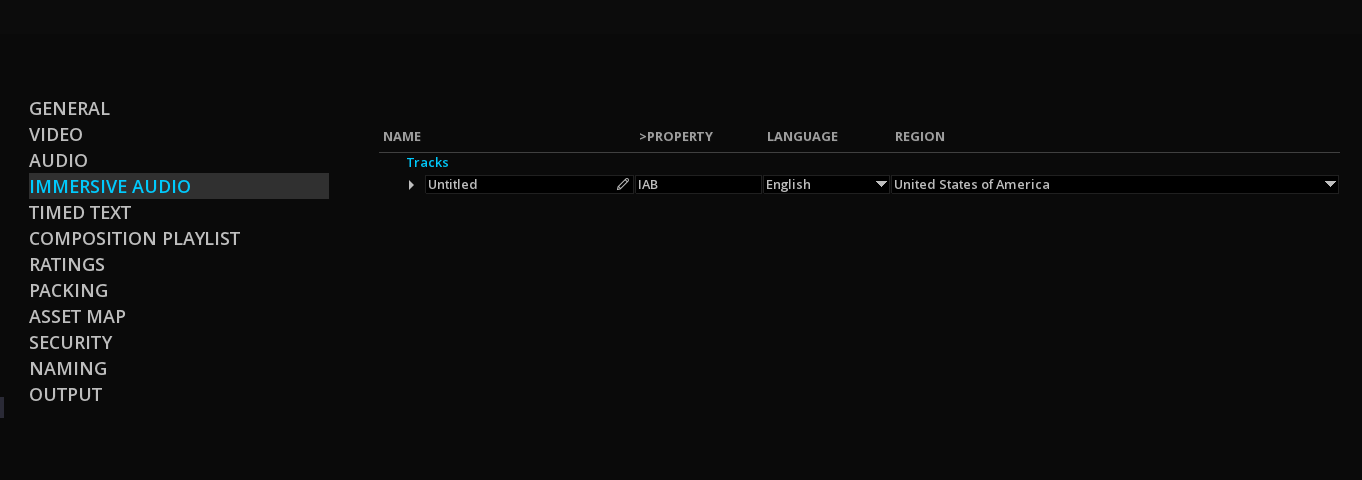
19.3.8. Timed Text
It is recommended to read also the chapter Subtitles & captions.
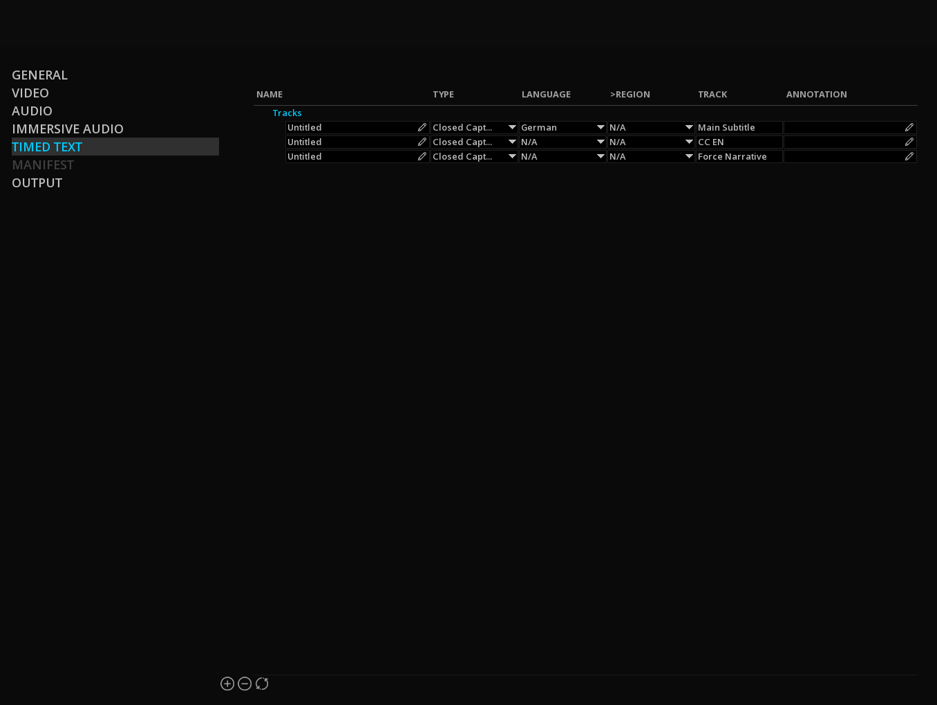
Track
MIST displays the Track name as set in the Layers Control Box in the timeline for a better identification of the tracks in the list.
|
See Timeline Configuration to learn how to rename layers |
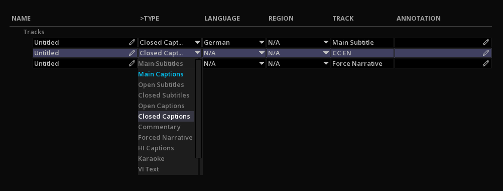
Subtitle Burn-In
In order to burn-in the image a particular subtitle, select "Burn-In" at the beginning of the Type drop-down menu:
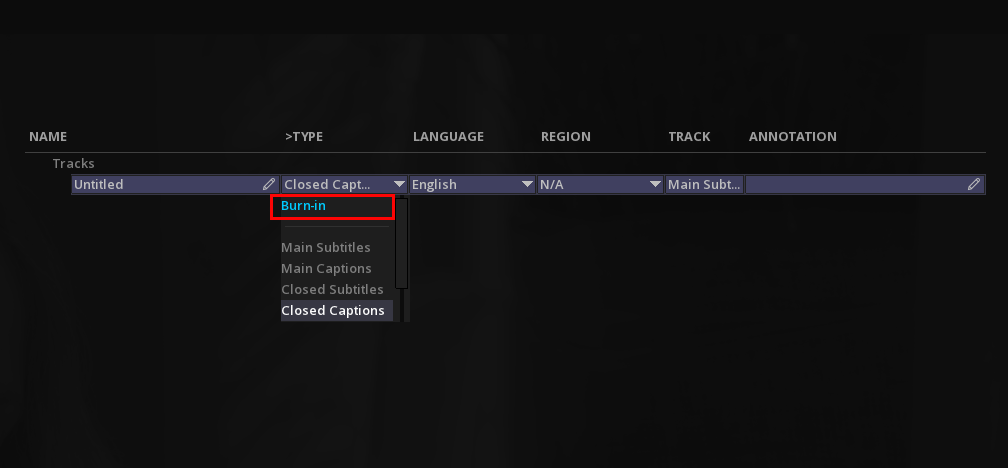
|
In order to have access to the Subtitle Burn-in option, the Composition must first be set on Compositing mode (see Composition Settings). |
19.3.9. Naming
It is possible, for each asset and metadata track to create a custom naming convention using tags.
By default, the tracks include the $PackageName$ tag.
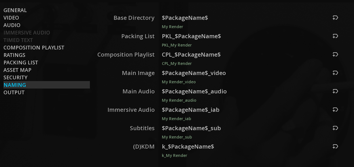
→ Click on the field for a specific track to edit it and position the cursor at the location you want to add a new tag, then click on the Add Tag icon at the end of the text field.
→ Select form the drop-down list the tag of your choice. The name preview is written in green below each name field.
|
You can add as many tags as you want, however make sure the metadata associated with the tags are correctly filled before you select a tag. The metadata are those of the Project, the Composition and the Master Delivery. |
|
It is better to separate each tag by an underscore. |
19.3.10. Output
The output page differs according to the type of format chosen, but content at minimum the following parameters :
| Destination |
click the HDD icon to browse MIST file system and select the location to render the file. |
| Mastering Report |
MIST can create a mastering report for each type of master.
|
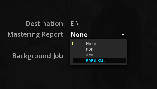
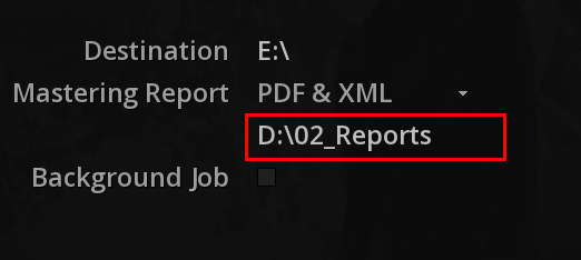
| Background job |
check the box to enable the background rendering. |
| Start the Render |
To start the rendering of your content, click MAKE. |
19.4. Special Deliveries
The following chapters provide detailed explanations on some of the masters that can be created from the Master Delivery Panel.
DCP and IMF packages are detailed in dedicated sections further:
19.4.1. Apple iTunes Package
To create an Apple iTune packages, when your timeline is ready to be exported, into the Master Delivery panel, select the Apple iTunes Package deliverable into the list. There are several pages to fill:
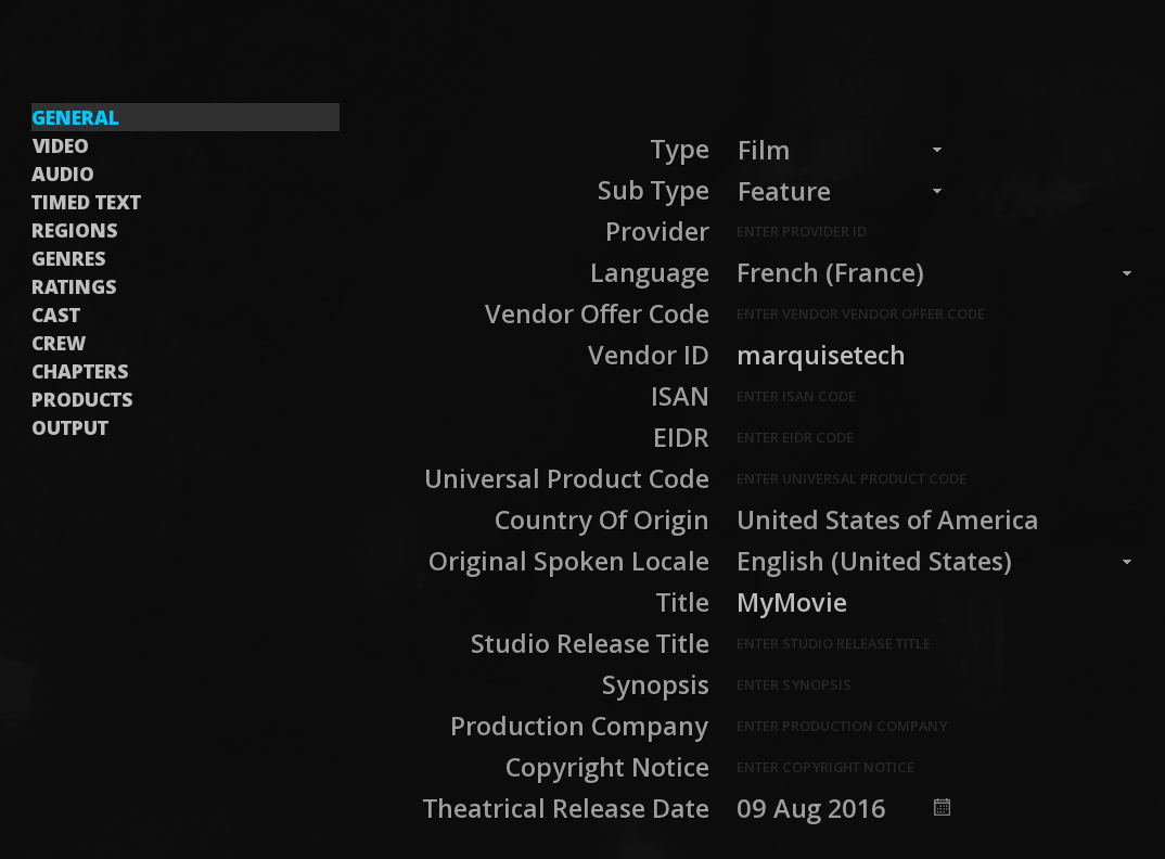
General
This page concerns the general film metadata to fill according to the iTunes specifications. Please read the iTunes specifications from Apple in order to help you to fill in the fields properly.
-
You can click on a drop-down menu to choose your setting or click on the empty field to be able to write information inside.
-
For the selection of calendar dates, just click on the calendar icon and select the desired one as soon as the calendar has opened:
-
Use the arrows to move through the calendar. A simple arrow will make you move from month to month while a double arrow will make you change year:
Video
MIST supports different profiles for Apple ProRes.
-
Select the Color encoding and Profile parameters using the drop down menus:
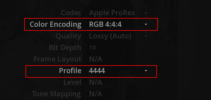
-
To select the Color Space, click on the current settings to open the drop-down menu and choose the desired one:
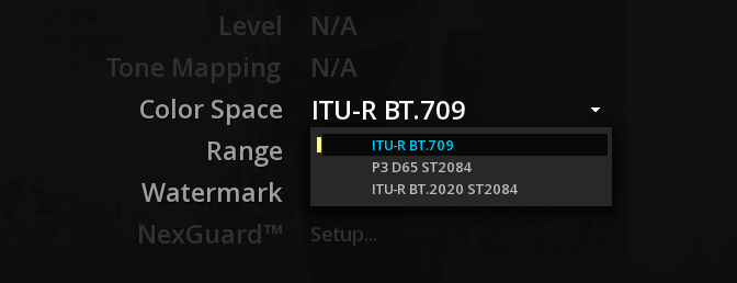
HDR settings
-
To be able to choose a HDR output, the Composition Settings must be compliant for a HDR workflow. If not, the HDR color space will not be present in the list.
-
If you select HDR10, the MaxFALL and MaxCLL values will be exported into the iTunes manifest.
-
If Dolby Vision is selected, a MDF file will be included into the iTunes package (see chapter Dolby Vision for reference).
Regions
The REGIONS page allows to manage the regional variation in theatrical release dates and copyright.
-
To add a region, simply click on the + button at the bottom left of the list.
-
To delete an existing region, click -. The third button allows to reset the current list.
-
Change the order by selecting the desired region in the list and clicking on the up or down arrow located at the bottom right.
Genres
The GENRES page allows you to choose the genre of the movie from an exhaustive list provided by Apple.
-
Select the desired genre by clicking on it on the list. Use the wheel scroll to move through the list:
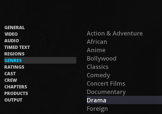
Ratings
The RATINGS page allows to define the rating of a movie. This page is working in the same way as REGIONS.
-
to edit the properties of an existing ratings, double-click on the property field column then write your information.
Cast
CAST allows to inform about the actors who performed work in the production. The operation of this page is similar to those mentioned previously.
-
Uses + and - buttons to add or delete a cast member. For each cast, double click on the text field to enter the information.
For each cast, it is possible to associate one or more characters by clicking on the + icon next to the Character field:
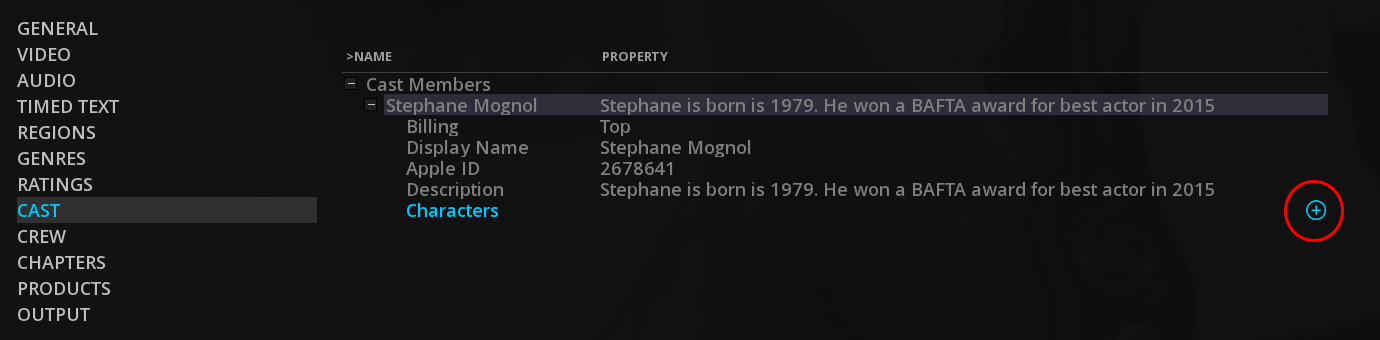
-
To attach an image for a character, click on N/A. MIST will open a window to allow you to choose the .png file to import:
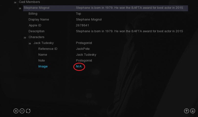
To delete a character without deleting all entries, click on the “-“ button associated to each of them:
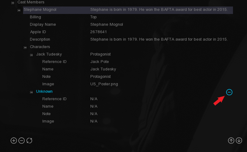
Crew
Like the CAST page, the CREW one allows to inform about the people who worked on the production by adding their Role:
-
Define a role with the drop-down menu by double clicking on the default role which is Co-Director:

Chapters
The CHAPTERS page allows to manage chaptering information. It consist of metadata (chapter start time and title) and images.
It is necessary to create the chapters first. To create chapters, use the Reel markers functionality of MIST (see REELS for reference).
-
To modify the properties of each metadata, double click on the concerned field.
-
To import an Artwork, double-click on N/A to open the import browser and select your png file.
-
You can’t change the Start time from this page. You must go back to the REELS tool.
-
You can add/delete one or more Titles for each chapter by clicking on the + or - buttons on the right of Titles.
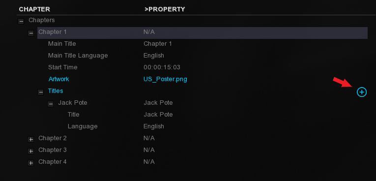
Products
-
Uses + and - buttons to add or delete a Product. For each Product, double click on the text field in the PROPERTY column to edit the information.
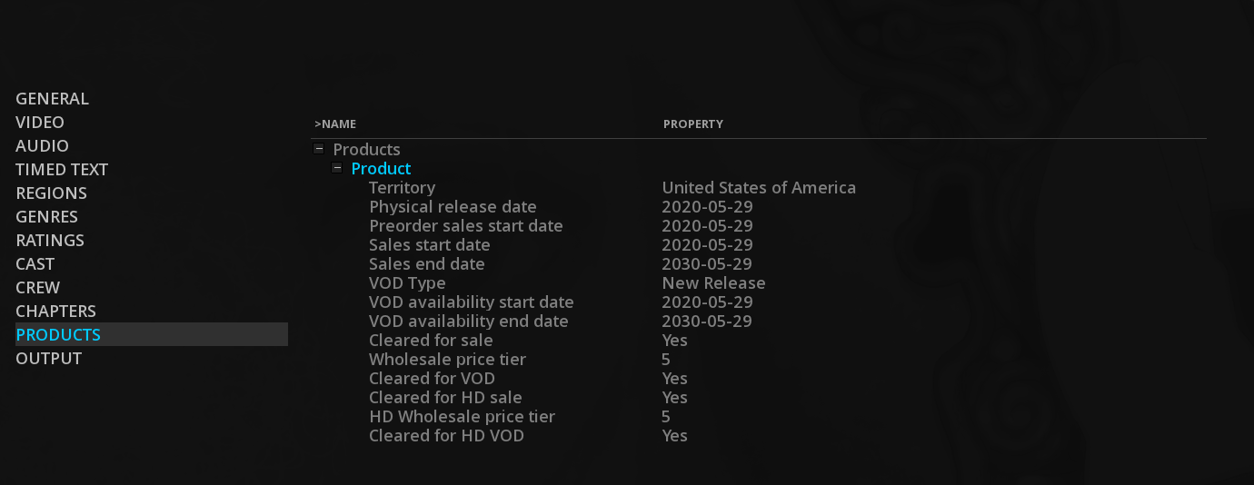
Output
The Output page is where you will define the destination directory for the iTunes package.
-
Click on the BROWSE icon on the right in order to define an output destination
-
Click MAKE to launch the export.
|
The package will be named using the Vendor ID field and finishing by “.itmsp”. The package contains the manifest, an XML file named metadata.xml that describes the delivered content as well as video, audio and subtitles assets. |
Update an iTunes Package
Metadata can be updated in an iTunes package without the need to re-encode the entire file. MIST will simply rewrap the package with the new metadata.
In order to do this, follow these steps:
-
Drop the iTunes package into the timeline.
-
Go to the Master Delivery panel and change your metadata information.
-
From the OUTPUT page, choose the iTunes package to update as destination.
-
Click on MAKE.
19.4.2. AS-10
This deliverable allows you to export an MXF OP-1a in AS-10 profile. AS-10 utilizes a single file format originating from Sony XDCAM HD that can be used by all production workflow components without the need to transcode or rewrap.
MIST allows to use five existing shim :
-
CNN HD 2012 (HD MP@HL 4:2:0 1440x1080)
-
NRK HD 2012 (HD422 422P@HL 4:2:2 1920x1080)
-
High HD 2014 (CANAL shim - similar to NRK HD 2012 but with 24bit PCM audio encoding)
-
JVC HD 35Mb VBR 2012 (HD MP@H-14 25_CBR 4:2:0 1440x1080)
-
JVC HD 25Mb CBR 2012 (HD MP@HL 35_VBR 4:2:0 1440x1080)
General
In this page, select the shim from the drop-down menu then fill in metadata.
| Type |
Describes the production category of clip. |
| Main title |
Main title associated with the clip. |
| Subtitle |
Sub title associated with the clip. |
| Title description |
Title description associated with the clip. |
| Organization name |
Fill in the name of the organization. |
| Person name |
Fill in the person name. |
| Location Description |
The text description of a location. |
| Spanning number |
Identifier for the spanning number. |
| Common spanning ID |
UMID (Unified Multi Purpose ID) for the total spanning clips. |
| Cumulative duration |
Cumulative duration of preceding spanning clips in Edit Units. |
Video
Configure the video settings of the output file.
| Codec |
The AS-10 format is MPEG 2. |
| Profile |
This setting will depend on the chosen shim. |
| Level |
This setting will depend on the chosen shim. |
| Quality |
Video bit rate will be 25_CBR, 35_VBR or 50_CBR depending the shim. |
| Bit depth |
The bit depth required is 8 bits. |
| Watermark |
Check this box if you want to enable watermarking. |
| NexGuard |
Available only if the watermarking checkbox has been checked. Click the Setup button to access the NexGuard Plus. You must have a NexGuard account. |
Metadata
This page allows you to add additional metadata requested by some broadcasters. This exaustive list is not definitive and already includes some broadcasters like France Television, Canal +, TF1 and M6.
If you need to fill in additional metadata for a broadcaster not mentionned, please write to support@marquise-tech.com
For information on how to fill in these metadata, please refer to the current broadcaster specifications.
19.4.3. AS-11
This page allows you to export an MXF OP-1a in AS-11 profile. In order to replace tapes, AS-11 has been created to define the constrained media files used for the delivery of finished media assets (Air Master).
For now, MIST allows the use of the following shims:
-
UK DPP SD (SD D-10 50 Mbit/s)
-
UK DPP HD (HD AVC-Intra Class 100)
Seven different pages allow you to setup the output:
| GENERAL |
Choose your shim and fill in editorial metadata. |
| VIDEO |
Configure your video settings. |
| AUDIO |
Configure your audio settings. |
| TIMING AND PARTS |
Define timing and parts. |
| ACCESS SERVICE |
Indicate the presence of audio descriptions or captions. |
| ADDITIONAL INFORMATION |
Indicate if the content has Textless elements etc. |
| OUTPUT |
Set your file destination and export. |
|
To access this specification, your composition must be set to 25 FPS. |
General
In this page, select the shim from the drop-down menu then fill in editorial metadata.
| Version |
The version of the AS-11 shim specification to which the associated MXF file conforms. |
| Series title |
The final title of a grouping of publishable assets. |
| Programme title |
The title of a Program Version for a specific purpose. |
| Episode title/ Number |
Final episode-name and or number used to identify an individual episode. |
| Production number |
The unique number used to identify an individual Programme Version. |
| Synopsis |
Descriptive summary of the content (no more than 250 characters suitable). |
| Originator |
Company responsible for creating the asset. |
| Copyright year |
Year (only) in which the production was completed. |
| Other identifier |
A unique code that can be used to identify a piece of content. |
| Type |
Description of other identifier (e.g. ISAN etc). |
| Genre |
A genre categorizing the whole asset. |
| Distributor |
The name of the company providing the content. |
For further information, please read the UK DPP specifications.
Video
Configure the video settings of the output file.
| Picture ratio |
Determine the editorial aspect ratio of the Program. |
| Product Placement |
This is to be set if the editorial content contains any product placement. |
| Comments |
The comments which illustrate the subjective quality and any known artefacts or defects (inc. intentional) within the video content discovered during production / post production / or any subsequent technical QC/Review process. |
| Watermark |
Check this box to activate the watermarking using NexGuard. |
| Stereoscopic 3D |
This allows the description of the type of 3D being delivered (if any). |
| PSE tested |
Status of any flashing and pattern analyser test carried out on the material for PSE (photosensitive epilepsy). |
| PSE manufacturer |
Product used to carry out the PSE analysis. |
| PSE version |
Version of algorithm used to carry out the PSE analysis. |
Timing and parts
| Material Start |
Type the number of the material start with the keyboard. |
| Line Up Start |
Timecode for start of line up test signals. |
| ID/Clock duartion |
Timecode for start of the initial ident or countdown clock. |
| Programme duration |
Total of all part durations. |
Access service
- Audio description
-
If the content to deliver contains any audio description for the visually impaired, click on YES then define the type of the audio description employed within the delivered programme from the dropdown menu.
- Closed captions
-
If the content to deliver contains any embedded (out of vision) subtitling information for the hard of hearing, click on YES then define the type of editorial description of the out of vision subtitling employed within the delivered programme. Select the primary language of the embedded subtitle data with the dedicated dropdown menu.
- Open captions
-
If the content to deliver contains any visible (in vision) subtitling information for the hard of hearing, click on YES then define the type of editorial description of the out of vision subtitling employed within the delivered programme. Select the primary language of the in vision subtitle data with the dedicated dropdown menu.
- Signing
-
If the content to deliver contains any in vision signing for the hard of hearing, click on YES then define the type of language used within the programme with the dropdown menu.
Additional information
- Textless elements
-
Click on YES if the delivered programme includes any textless elements.
- Programme text
-
Used to identify if the main programme is free of any text. If there is text, you can define its language with the dedicated dropdown menu.
- Completion and contact information
-
Add the completion date, the email address and phone number of the SPOC (Single Point Of Contact) for the use of the recipient regarding any delivery or technical issues encountered with the delivered file.
19.4.4. MXF Master for CANAL+
MIST can create an MXF master file that meets CANAL+ specifications.
General
In this page, you can name your MXF file and choose the specifications. Select CANAL+ from the drop-down menu labeled Specification.
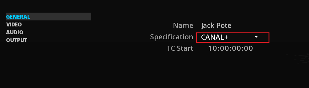
|
To access this specification, your composition must be set to UHD 25p or 50p. |
Then the TC START must be set according to the specification.
Video
Configure the video settings of the MXF master file. According to the possibilities granted by the CANAL+ specification, you will be able to select the desired settings.
| Codec |
Only the H.264 codec is possible. It is the video standard used by XAVC. |
| Profile |
The profile required is XAVC Intra CBG profile (Constrained Bytes per GOP). |
| Quality |
Sets the quality for 25p or 50p frame rate. |
| Bit depth |
The bit depth required is 10 bits. |
| Range |
Select the color range. |
| Color Space |
The color space required is Rec709. |
| Primaries |
The primaries are configured according to the chosen color space. |
| Transfer |
The transfer is configured according to the chosen color space. |
| Matrix |
The matrix is configured according to the chosen color space. |
| Watermark |
Check this box if you want to enable watermarking. |
| NexGuard |
Available only if the watermarking checkbox has been checked. Click the Setup button to access the NexGuard Plus. You must have a NexGuard account. |
Audio
Configure the audio settings of the MXF master file. According to the possibilities granted by the CANAL+ specifications, you will be able to select the desired settings.
| Codec |
The audio codec must be in PCM 24bit.
|
19.4.5. MXF Master for FOX
Choose this output to deliver an MXF master file that meets Fox specifications. From here, it is possible to export several types of MXF OP-1a outputs for different FOX divisions such as archives or servicing.
General
In this page, you can name your MXF file and choose the specifications. Select FOX from the drop-down menu labeled Specification.
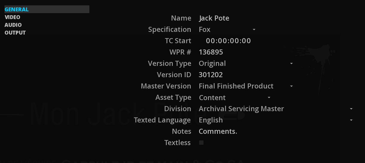
| TC Start |
Select the start timecode of the program. |
| WPR # |
Stands for "World Wide Product Registry Number". Type the unique number given by Fox. |
| Version Type |
It the type of the version of the Title. Click on the drop-down menu to select the desired one. |
| Version ID |
Unique number given to each version of each title. |
| Master Version |
The Source that the file was created from. Click on the drop-down menu to select the desired one. |
| Asset Type |
The type of program material in the asset. Click on the drop-down menu to select the desired one. |
| Division |
The division for which the file is created. As for example, the Archival Servicing Master whom the purpose is to replace tape. |
| Texted Language |
Language displayed on screen as intended for a native speaking viewer. |
| Notes |
Any additional information about the file. |
| Textless |
Check this box when an asset is completely textless from beginning to end (not just containing Textless material at the end of program). |
Video
Configure the video settings of the MXF master file. According to the possibilities granted by the FOX specifications, you will be able to select the desired settings.
| Codec |
Only the JPEG2000 deliveries are available. |
| Profile |
The profile required is profile 2. |
| Quality |
The profile required is lossless. |
| Bit depth |
The bit depth required is 10 bits. |
| Color Encoding |
The color encoding required is 422. |
| Range |
The color range required is HEAD (Legal Range). |
| Color Space |
The color space required is Rec709 for HD files or Rec601 for SD files. |
| Primaries |
The primaries are configured according to the chosen color space. |
| Transfer |
The transfer is configured according to the chosen color space. |
| Matrix |
The matrix is configured according to the chosen color space. |
| Watermark |
Check this box if you want to enable watermarking. |
| NexGuard |
Available only if the watermarking checkbox has been checked. Click the Setup button to access the NexGuard Plus. You must have a NexGuard account. |
Audio
Configure the audio settings of the MXF master file. According to the possibilities granted by the FOX specifications, you will be able to select the desired settings.
| Codec |
The audio codec must be in PCM 24bit.
|
19.4.6. MXF Master for HBO
Choose this output to deliver an MXF master file that meets HBO specifications.
General
In this page, you can name your MXF file and choose the specifications. Select HBO from the drop-down menu labeled Specification.
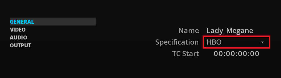
Video
Configure the video settings of the MXF master file. According to the possibilities granted by HBO specifications, you will be able to select the desired settings.
| Codec |
Only the JPEG2000 deliverie is available. |
| Profile |
The profile required is profile 2. |
| Quality |
The profile required is lossless. |
| Bit depth |
The bit depth required is 10 bits. |
| Color Encoding |
The color encoding required is 422. |
| Range |
The color range required is HEAD (Legal Range). |
| Color Space |
The color space required is Rec709. |
| Primaries |
The primaries are configured according to the chosen color space. |
| Transfer |
The transfer is configured according to the chosen color space. |
| Matrix |
The matrix is configured according to the chosen color space. |
| Watermark |
Check this box if you want to enable watermarking. |
| NexGuard |
Available only if the watermarking checkbox has been checked. Click the Setup button to access the NexGuard Plus. You must have a NexGuard account. |
Audio
Configure the audio settings of the MXF master file. According to the possibilities granted by the HBO specifications, you will be able to select the desired settings.
| Codec |
The audio codec must be in PCM 24bit.
|
19.4.7. QuickTime Master for Amazon Prime
Choose this output to deliver a Quicktime master file that meets Amazon Prime HDR specifications.
General
In this page, you can name your file and choose the specifications. Select Amazon Prime from the drop-down menu labeled Specification.
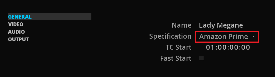
|
Be sure to have your FORMAT Composition settings set on UHD format. |
Then the TC START is setup according to the specification.
By checking the Fast START box, the file will be able to be played before all of its data has been received. Used for especially for streaming.
Video
Configure the video settings of the QuickTime Master file. According to the possibilities granted by the Amazon Prime HDR specifications, you will be able to select the desired settings.
| Codec |
Amazon Prime requires Apple ProRes codec. |
| Profile |
The profile required is ProRes 4:2:2 HQ. |
| Quality |
Quality is defined regarding the codec and profile used. |
| Bit depth |
The bit depth required is 10 bits. |
| Range |
The color range is setup to Head. |
| Color Space |
The color space required is Rec2020. |
| Primaries |
The primaries are configured according to the chosen color space. |
| Transfer |
The transfer is configured according to the chosen color space. |
| Matrix |
The matrix is configured according to the chosen color space. |
| Watermark |
Check this box if you want to enable watermarking. |
| NexGuard |
Available only if the watermarking checkbox has been checked. Click the Setup button to access the NexGuard Plus. You must have a NexGuard account. |
Audio
Configure the audio settings of the QuickTime Master file. According to the possibilities granted by the Amazon Prime specifications, you will be able to select the desired settings.
| Codec |
The audio codec must be in PCM 24bit.
|
19.4.8. QuickTime Master for Disney
Choose this output to deliver a Quicktime master file that meets Disney ProRes HQ SDR and XQ HDR master specifications.
General
In this page, you can name your file and choose the specifications. Select Disney from the drop-down menu labeled Specification.
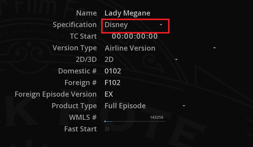
|
Be sure to have your FORMAT Composition settings set on UHD 23,976 fps or HD 23,976 fps format. |
Then the TC START is setup according to the specification.
| Version Type |
The Version field denotes either the version of the feature content or the episode number and version for episodic/TV content. |
| 2D/3D |
Indicate if it is a 2D or 3D version. |
| Domestic |
Fill in the numbers provided. |
| Foreign |
Fill in the numbers provided. |
| Foreign Episode Version |
Fill in the episode version (PL for Pilot short, EX for extended version etc.) |
| Product type |
The ProductType field is only used for folders and gives a brief description of what the folder contains. |
| WMLS |
Fill the WMLS Element ID number. |
By checking the Fast START box, the file will be able to be played before all of its data has been received. Used for especially for streaming.
For more information, please refer to Disney specifications. The metadata in the general page will be used to fill in the necessary information used for the naming convention.
Video
Configure the video settings of the QuickTime Master file. According to the possibilities granted by the Disney specifications, you will be able to select the desired settings.
| Codec |
Disney requires Apple ProRes codec. |
| Profile |
The profile required is ProRes 4:4:4:4 XQ or HQ depending on your output settings. |
| Quality |
Quality is defined regarding the codec and profile used. |
| Bit depth |
The bit depth required is 10 bits. |
| Range |
The color range is setup to Head. |
| Color Space |
Select the color space required in Rec2020 or Rec709. |
| Primaries |
The primaries are configured according to the chosen color space. |
| Transfer |
The transfer is configured according to the chosen color space. |
| Matrix |
The matrix is configured according to the chosen color space. |
| Watermark |
Check this box if you want to enable watermarking. |
| NexGuard |
Available only if the watermarking checkbox has been checked. Click the Setup button to access the NexGuard Plus. You must have a NexGuard account. |
Audio
Configure the audio settings of the QuickTime Master file. According to the possibilities granted by the Disney specifications, you will be able to select the desired settings.
| Codec |
The audio codec must be in PCM 24bit.
|
19.4.9. QuickTime Master for Fox
Choose this output to deliver a Quicktime master file that meets Fox ASM ProRes deliveries specifications (excepting ASM in UHD for now).
General
In this page, you can name your file and choose the specifications. Select Fox from the drop-down menu labeled Specification.
|
Be sure to have your FORMAT Composition settings set on SD NTSC in 23,976 or 29,97 fps, SD PAL in 25 fps or HD in 23,976 fps format. |
| TC Start |
Select the start timecode of the program. |
| WPR # |
Stands for "World Wide Product Registry Number". Type the unique number given by Fox. |
| Version Type |
It the type of the version of the Title. Click on the drop-down menu to select the desired one. |
| Version ID |
Unique number given to each version of each title. |
| Master Version |
The Source that the file was created from. Click on the drop-down menu to select the desired one. |
| Asset Type |
The type of program material in the asset. Click on the drop-down menu to select the desired one. |
| Division |
The division for which the file is created. As for example, the Archival Servicing Master whom the purpose is to replace tape. |
| Texted Language |
Language displayed on screen as intended for a native speaking viewer. |
| Notes |
Any additional information about the file. |
| Textless |
Check this box when an asset is completely textless from beginning to end (not just containing Textless material at the end of program). |
| Fast Start |
By checking the Fast START box, the file will be able to be played before all of its data has been received. Used for especially for streaming. |
Video
Configure the video settings of the QuickTime Master file. According to the possibilities granted by the Fox specifications, you will be able to select the desired settings.
| Codec |
The codec is setup to Apple ProRes. |
| Profile |
The profile required is HQ 4:2:2. |
| Quality |
Quality is defined regarding the resolution used. For SD select 70 Mbps, for HD choose 220 Mbps. |
| Bit depth |
The bit depth required is 10 bits. |
| Range |
The color range is setup to Head. |
| Color Encoding |
The color space required is Rec709 for HD. However, if using SD format you can select Rec601 either. |
| Primaries |
The primaries are configured according to the chosen color encoding. |
| Transfer |
The transfer is configured according to the chosen color encoding. |
| Matrix |
The matrix is configured according to the chosen color encoding. |
| Watermark |
Check this box if you want to enable watermarking. |
| NexGuard |
Available only if the watermarking checkbox has been checked. Click the Setup button to access the NexGuard Plus. You must have a NexGuard account. |
Audio
Configure the audio settings of the QuickTime Master file. According to the possibilities granted by the Fox specifications, you will be able to select the desired settings.
| Codec |
The audio codec must be in PCM 24 bit.
|
19.4.10. QuickTime Master for NBC Universal
Choose this output to deliver a Quicktime master file that meets NBC Universal HDR specifications.
General
In this page, you can name your file and choose the specifications. Select NBC Universal from the drop-down menu labeled Specification.
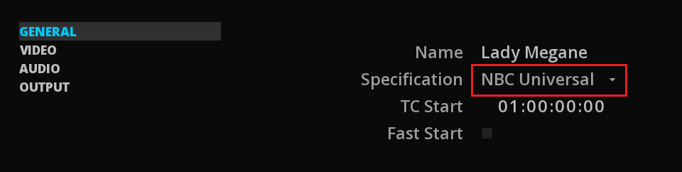
|
Be sure to have your FORMAT Composition settings set on UHD format. |
Then the TC START is setup according to the specification.
By checking the Fast START box, the file will be able to be played before all of its data has been received. Used for especially for streaming.
Video
Configure the video settings of the QuickTime Master file. According to the possibilities granted by the NBC Universal HDR specifications, you will be able to select the desired settings.
| Codec |
NBC Universal requires Apple ProRes codec. |
| Profile |
The profile required is ProRes 4:4:4:4. |
| Quality |
Quality is defined regarding the codec and profile used. |
| Bit depth |
The bit depth required is 12 bits. |
| Range |
The color range is setup to Full. |
| Color Space |
The color space required is Rec2020. |
| Primaries |
The primaries are configured according to the chosen color space. |
| Transfer |
The transfer is configured according to the chosen color space. |
| Matrix |
The matrix is configured according to the chosen color space. |
| Watermark |
Check this box if you want to enable watermarking. |
| NexGuard |
Available only if the watermarking checkbox has been checked. Click the Setup button to access the NexGuard Plus. You must have a NexGuard account. |
Audio
Configure the audio settings of the QuickTime Master file. According to the possibilities granted by the NBC Universal specifications, you will be able to select the desired settings.
| Codec |
The audio codec must be in PCM 24bit.
|
19.4.11. QuickTime Master for Netflix
Choose this output to deliver a QuickTime master file that meets Netflix MPEG 2 delivery specifications.
General
In this page, you can name your file and choose the specifications. Select Netflix from the drop-down menu labeled Specification.
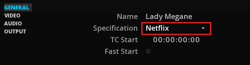
Then the TC START is setup according to the specification.
By checking the Fast START box, the file will be able to be played before all of its data has been received. Used for especially for streaming.
Video
Configure the video settings of the QuickTime Master file. According to the possibilities granted by the Netflix specifications, you will be able to select the desired settings.
| Codec |
The codec is setup to MPEG 2. |
| Profile |
The profile required is 4:2:2. |
| Level |
The level required is High. |
| Quality |
Quality is defined regarding the resolution used. For HD, choose 80 Mbps and for SD, select 50 Mbps. |
| Bit depth |
The bit depth required is 10 bits. |
| Range |
The color range is setup to Head. |
| Color Space |
The color space required is Rec709. However, if using SD format you can select Rec601 either. |
| Primaries |
The primaries are configured according to the chosen color space. |
| Transfer |
The transfer is configured according to the chosen color space. |
| Matrix |
The matrix is configured according to the chosen color space. |
| Watermark |
Check this box if you want to enable watermarking. |
| NexGuard |
Available only if the watermarking checkbox has been checked. Click the Setup button to access the NexGuard Plus. You must have a NexGuard account. |
Audio
Configure the audio settings of the QuickTime Master file. According to the possibilities granted by the Netflix specifications, you will be able to select the desired settings.
| Codec |
The audio codec must be in PCM 16 bit.
|
19.5. Delivery Presets
All the properties of an export can be saved as Preset.
-
To save a new preset, use SAVE at the bottom of the Delivery Panel:
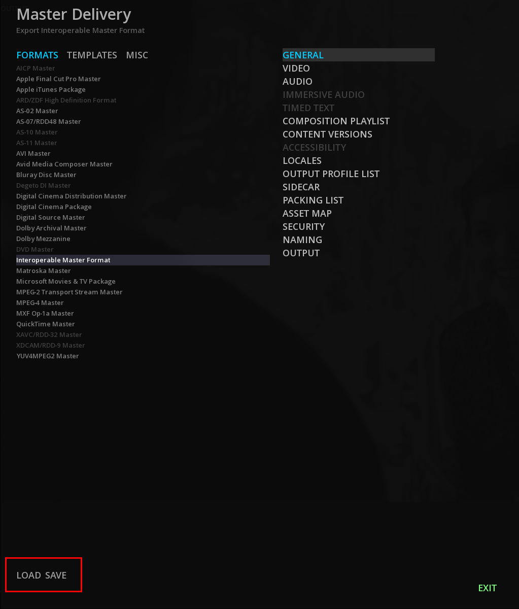
By default the Delivery Presets are saved in the following location:
C:\Users\"UserName"\AppData\Roaming\Marquise Technologies\presets\deliverables
-
To apply a Preset for a new delivery, use LOAD, select the Preset and click OK.
19.6. Background Rendering
![]()
The background rendering feature allows to start the rendering of the deliverable in background, in order to continue working with MIST.
If this option is checked in the OUTPUT page of the Master Delivery panel, when pressing MAKE MIST will immediately start the rendering transparently in background.
-
To display the background rendering Render Queue, press F4:
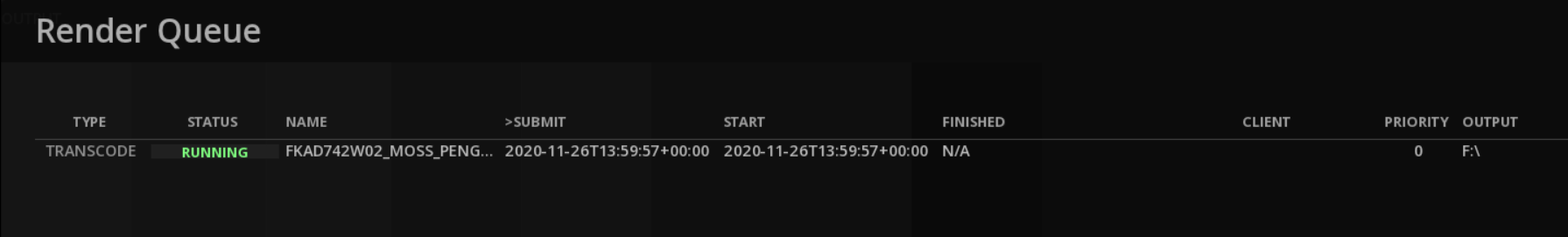
-
To delete a job, select the desired job and press delete
|
To enable background rendering for MIST Studio, StormServer service must be installed at MIST’s installation (see Software Installation). |
19.7. Rewrapping media
Any video file can be rewrapped in another format very easily using the Rewrap function.
→ In the media bin, right click on the video file and select Rewrap… from the menu.
This will open the Master Delivery panel, with a choice of format limited and constrained according to the codec properties (codec, bit rate, quality, etc.) of the original media.
MIST allows to add all the descriptive and technical metadata required by the master and to rewrap the media without re-encoding it.
20. DCI MASTERING
This chapter is a user guide for DCI Mastering with MIST.
20.1. DCP management in MIST
MIST allows you to create content that adheres to the specifications of the Digital Cinema Initiatives (DCI) and is compliant with the SMPTE standards for digital cinema. It also gives you the ability to import an existing DCP for review, quality control and potentially the creation of a new version for localization or other purposes.
It also permit the repair and the rewrapping of exisitng DCPs
20.1.1. Color management
The selection of the input color space for DCP creation is managed from the Color Management System (CMS) in the Compositions Settings.
By defining the color space of the original media in the timeline, MIST will use it as a starting point for converting your content to the DCI XYZ color space, therefore this setting has a tremendous influence on the successful conversion of colors.
For more information on how MIST manages color spaces, refer to the chapter Color Management.
From XYZ sources
If you are working from an XYZ source (e.g. an existing DCP) and the encoding does not require any color conversion, you must use the Native color system.
The video track will not be re-encoded when exporting the DCP and the settings entered in the Color space of the VIDEO page of the DCP export panel will only serve as metadata.
However, if a source with RGB primaries is mixed to an XYZ content (e.g. an insert in Rec709), it is recommended to use the MTCMS color management system rather than using a LUT.
From RGB sources
When the content of a composition involves the use of sources in RGB primaries, these sources must be converted to XYZ when creating the DCP. To do this, it is possible to use the MTCMS color management system or the ACES one.
-
Using MTCMS:
-
you must define the working color space and the response transfer curve of your composition. For example, if we take the case of content in Rec709, you can select the Rec709 as working color space and its transfer response curve. However, selecting DCI P3 instead remains the best option and will allow you to have a preview upstream of the conversion done during the DCP processing. In particular the change of white point from D65 to DCI, whereas choosing the Rec709 does not allow you to see this transformation.
-
As explained previously, do not forget to select your method of chromatic adaptation for the white point via the drop down menu. To know which one to choose, please refer to the chapter Color Management / MTCMS.
-
Define the luminance levels of the composition.
-
From the SOURCE tab of the GRADE panel, define the properties of your content in order to set this color space as starting point for the color conversion. In our example, content is in Rec709.
-
In the Master Delivery, in the VIDEO page, select the output Color space to which MIST will convert from the MTCMS settings.
-
-
Using the ACES color system:
-
Select the ACES system in the CMS tab of the Composition settings.
-
From the SOURCE tab of the GRADE panel, define the Input Device Transform matching to your source via the drop-down menu.
-
In DELIVER / Digital Cinema Package / VIDEO page, select the output Color space to which MIST will convert from ACES.
-
20.1.2. Video Output
MIST allows the monitoring of the DCP creation process by connecting the SDI output of the video board to either a DCI or a compliant broadcast monitor.
The projector must be set up to receive XYZ color space, 4:4:4 input from an external video source.
For more information please read chapter Video Output.
Setting up the dual-link 4:4:4 display in MIST
Once your MIST workstation has been properly connected to the display device, you must select the output signal and mode. This is done in the Project Settings then Video Output page.
To verify the framing on a digital cinema projector, you must select a 2K or 4K signal in the appropriate presentation (e.g. scope, flat etc) that matches the frame rate of your DCP. Please note that although 24fps is the de facto standard for DCPs, it is now possible to have other frame rates as well. It is not uncommon to have 25fps in Europe. It is quite possible that not all projectors support such frame rates, although this is changing rapidly.
The next step is to select the format of the signal, which defines the color depth resolution. While it is possible to use a 4:2:2 format for a preview, it is strongly advised not to do so if you want to verify the colorimetry. A video signal that uses 4:2:2 color sampling, will clearly drop half of the chromatic part of the color (while keeping luminance intact) and therefore is not a good choice. Proper monitoring can only be achieved by using a 4:4:4 color depth resolution format. Depending on your configuration, you may either chose RGB 4:4:4 (if you are using a reference monitor), or XYZ 4:4:4 (in the case of a digital cinema projector).
Display using a DCI compliant projector
The following diagram shows the basic installation for performing a quality control check using MIST and a DCI P3/P7 compliant digital cinema projector. There are two possible cases that may need a QC before any DCP is generated.
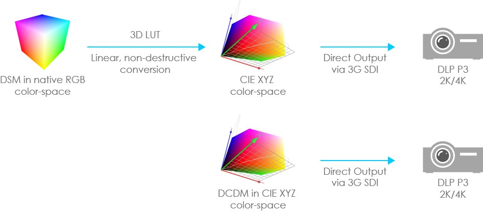
-
The first case is when the DSM is assembled in the timeline, using its native RGB color space. A 3D LUT is used to perform the color conversion from the DSM’s native color space to the DCI P3 XYZ color space. This LUT is loaded in the Calibrate panel in MIST. Once this is done, the following (non-exhaustive) list of properties may be checked:
-
The second case is when the DSM assembled in the timeline is already in the DCI XYZ color space, meaning that it is a DCDM.
By nature, a DCDM is already in the DCI XYZ color space. However the same comments as for the first case apply. This is especially true if the DCDM has been made somewhere outside MIST and very little information is available about that stage of the process.
Displaying a DCDM on a DCI compliant projector will show no color issues, unless these have been intended.
In order to make sure that there has been no error on that side, it is a good practice to compare with a version of the original DSM displayed on a monitor that is capable of showing the DSM’s color space and gamut.
20.1.3. DCP Reel management
To learn how to create, delete and manage reels, please read the chapter Reel Management.
|
Any portions of clips that are outside of a reel marker will not be exported at all. This means that the picture, audio and subtitle essences are processed as independent blocks for each reel so instead of having a single .mxf essence file per CPL you end up with a separate .mxf picture, sound and subtitle essence per reel. |
20.2. Exporting a DCP
Once the DSM has been properly assembled in the timeline, you can move on to the packaging. In order to do this you must use the Master Delivery panel and choose Digital Cinema Package.
20.2.1. Accessing the Master Delivery panel
The Master Delivery panel is accessible through the DELIVER button located at the bottom of the timeline representing your composition.
When the Digital Cinema Package is selected, you can see the different settings required for the DCP creation.
20.2.2. General
In this page you will be able to define the general information about your DCP. Here is an overview of the GENERAL panel:
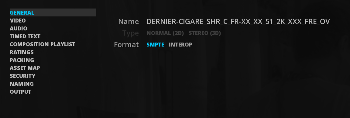
| Name |
Choose a Name for the DCP. by default, the name is taking the project name. |
| Specification |
To create a HDR DCP, use Specification Dolby or Eclair. |
| Presentation |
Allows you to select if you want to create a regular 2D DCP or a Stereo3D DCP. This option is enabled only if the composition is set for stereoscopy. |
| Format |
Allows you to create either an SMPTE or an Interop DCP. By default, MIST sets this parameter to SMPTE because any newly generated DCP will be SMPTE compliant. However for the sake of backwards compatibility, Interop DCPs are possible as well. |
|
There are some differences between the InterOp DCPs and the SMPTE DCPs, including the difference in the extension of the VOLINDEX and ASSETMAP xml files. Unlike the InterOp DCP, the .xml extension will be present in the names of these files for a SMPTE DCP. Do not mix those formats. |
20.2.3. Video
The Video settings are constraints according to the Specification chosen.
However you still need to select the desired output color space, bit rate and active area.
Bit Rate
Due to the technology involved in the construction of the majority of the first generations of DCI compliant servers deployed in theatres all over the world, JPEG2000 compression algorithm by the DCI specifications are set to 250 Mbit/s. If exceeding the bit rate currently certified by the DCI, most older generation playout servers will not currently be fast enough to decode and playout picture at this higher bit rate and the DCP will be rejected by the distribution chain or the servers themselves.
In MIST the Bitrate slider’s values range from 50 bps to 640 bps. By default, the maximum bitrate per frame is set to 250Mbit/s and 125Mbit/s for Stereo3D DCPs. If needed this limit may be decreased or increased. Please note that decreasing the limit may lead to serious picture quality degradation. Use it at your own risks!
Some applications make use of DCPs for archiving purposes and therefore need to create higher-quality DCPs. encoding in a higher bitrate allows you to store material that is essentially compliant with the DCI guidelines for use as archived material regardless of first generation DCI playout system limitations. If needed the high-bitrate DCP can always be decoded and re-encoded to lower bitrates for a DCI.
Color Space
Digital cinema projectors from various brands utilize various technologies for color reproduction. The DCI specification mandates DCI compliant projectors to be capable of displaying the standard DCI color space.
| DCI P3 |
The DCI P3 color space (SMPTE RP 431-2-2007) was the original specification. Most of the current digital cinema projectors are only capable of targeting this color space. |
| DCI P7 (v2) |
The DCI P7 color space is a refinement done by Texas Instruments on the original DCI P3 standard through the addition of secondary color specifications (i.e. cyan, magenta and yellow). The DCI P7 has the advantage of being more accurate at representing saturated hues in the cyans, magentas and yellows. Modern digital cinema display setups are capable of targeting the DCI P7 color space. |
| Dolby Cinema DCI |
This is the color space for the Dolby Cinema DCI. |
| Dolby Cinema EDR |
This is the color space for the Dolby Cinema EDR standing for Extended Dynamic Range. |
| Eclair Color EC1 EDR |
This is the color space for the Eclair Color HDR EDR for Extended Dynamic Range. The contrast is considerably superior to traditional digital cinema projectors, allowing for brighter whites and darker blacks. |
| Eclair Color EC1 HDR |
This is the color space for the Eclair Color High Dynamic Range, a display system with dynamic range comparable to modern TVs. |
|
As explained in the DCI Composition settings section, if using Native color managment system, the defined output color space in the DCP Master Delivery will only add metadata to the package, and will not perform any color processing on the video. |
Screen and Peak Luminance
DCinema uses a color encoding defined in the SMPTE ST428-1 standard and takes into account the screen luminance and peak luminance ratio.
Screen Luminance indicates the normal value of luminance which was used to author the content. The peak luminance indicates the maximum luminance that the theater projector can display. For a calibrated standard projection, they are respectively set to 48 cd/m2 and 52.37 cd/m2. Thus, it is possible to encode DCPs for situations that differ from those of cinemas. (e.g. an outdoor projection).This information is used in particular for calculating the RGB to XYZ transformation.
|
If you are outputting XYZ data from other software (e.g. Da Vinci Resolve), be sure to have it set to DCI specifications (meaning that the luminance and peak luminance factor are took into account during the conversion). Otherwise, the XYZ data will be simply encoded with a gamma 2.6 without a white adjustment resulting a brighter DCP. |
Active Frame
This setting allows you to choose if the height and width of the active picture area (visible picture) has to be FULL or based on BLANKING. Click on the desired setting. The one selected is highlighted in cyan.
This setting does not apply any modification to the image but adds a metadata in the CPL.
If choosing BLANKING, go to the FORMAT tab of the Composition Settings to setup the Active Area Aspect.
The FULL setting will use the full resolution used as output.
20.2.4. Audio
This page allows to set the audio settings for the DCP.
There is some particularities with audio for DCP, that are detailed below.
Language
If you add audio tracks to your DCP, it is strongly recommended that you select the proper audio language for it as well. Again, this is purely optional and it does not affect how a DCP is ingested; however it is good to tag the audio properly.
The audio language may be displayed by the digital cinema server making it easier for the operator to identify the content for playout.
The selected language is not only used in the composition playlist, but is also used in the title of the composition playlist when the Force Naming convention is selected.
SMPTE Labels
The SMPTE DCP standard includes an audio channel labeling system that indicates the intended channel assignment with an easy to understand acronym-lettered code that is displayed in the interface of an SMPTE compliant DCI server. This channel order display allows for the projectionist to properly verify and assign audio channels for playout of SMPTE compliant DCPs.
If you have chosen to create an SMPTE compliant DCP then MIST automatically labels the audio channels according to the SMPTE DCP standard. If you are creating an INTEROP compliant DCP than activating audio labels will not have any effect on the final DCP whether you chose YES or NO because of the lack of audio labels in the INTEROP standard.
|
INTEROP vs. SMPTE : Be aware that as of the publication of this document version, the vast majority of DCI compliant servers deployed actively in the world are INTEROP compliant and not SMPTE. If you wish to use the SMPTE format of DCPs to benefit from the improvements implemented therein then you must first confirm that the designated recipients of the DCPs you create possess SMPTE compliant DCI servers. Otherwise you can expect features specific to the SMPTE standard (such as audio labels) and even entire SMPTE DCPs to be rejected by INTEROP playout servers. |
Configuration
Select the desired audio configuration for your DCP up to 16 channels of audio like the DCI recommends.
The audio configuration parameter provides a last-minute possibility to configure the audio mapping for the DCP. While you may or may not have audio tracks in your composition, MIST allows you to create DCPs with blank audio tracks. In the case where your composition does not have any audio content, the audio tracks created in the DCP will be filled in with silence.
|
The DCI specifications have defined two possible sample rates, 48kHz and 96kHz. The current version of MIST, as of the creation of this document, will always generate 48kHz. Any audio media in the composition with a different sample rate will be resampled to 48kHz. It is important to remember that the best results will always be obtained by providing original audio tracks sampled at 48kHz. Resampling in MIST may produce audible artifacts or gain issues in some audio frequencies. Audio mastering is not part of the MIST feature set and therefore great care should be taken to insure that the quality of your audio channels are not compromised by resampling artifacts. |
20.2.5. Timed Text
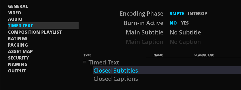
This page is used to select the subtitle track to be included in the DCP and to define the nature of its encoding.
It is recommended to read also the chapter Subtitles & captions.
|
Please note that if you are creating subtitles with a font type face that consists of non-occidental characters (such as: Chinese, Japanese, Cyrillic, Greek, Hindi etc.) then it is highly recommended to deliver the font type face along with the DCP and include special instructions as per how to install them on the particular D-Cinema player that you have created the DCP for. In many cases this may be a risky and tedious process, especially if you do not have the means to test your font type face on each type of D-Cinema player that you are creating DCPs for. The alternative is to create a version of your DCP with the subtitle track burnt directly into the picture essence as a security measure. |
|
Main Caption track (Open Caption) as well as Closed Subtitles tracks are only available for SMPTE’s DCP. The closed subtitles could carry alternative subtitles (e.g. for different languages) and are selectable by the projectionist (if the installation allows) in order to replace and/or complement the main subtitle track. |
20.2.6. Composition Playlist
In the composition playlist page, you can set the parameters and metadata of the CPL that is to be created from the clips placed in the current composition timeline in MIST.
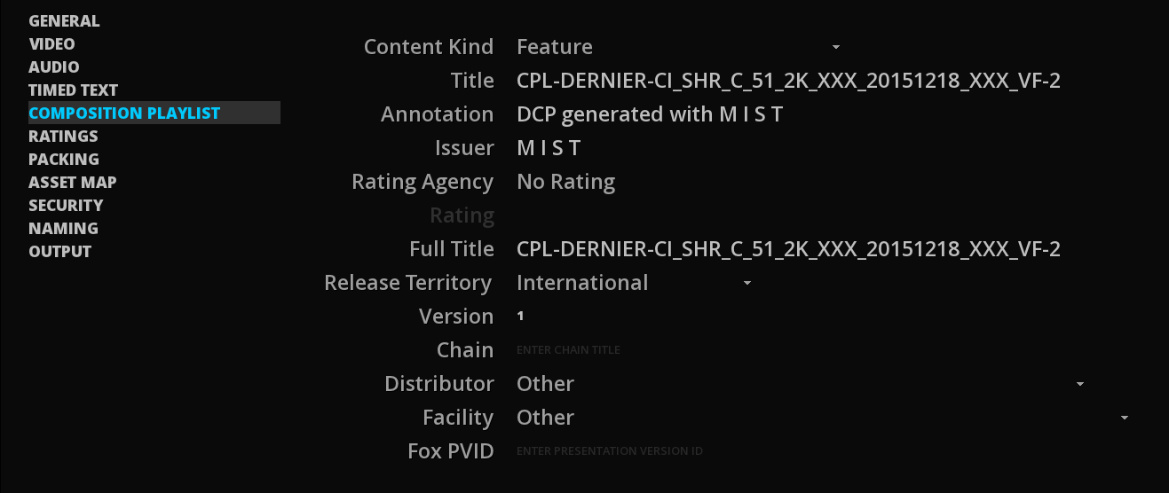
The metadata of a composition playlist is very important as they are used to display the contents of the DCP in a digital cinema server. Any mistake here can create issues in the theaters, even if the DCP is perfectly valid. These issues are not technical, but rather how the DCP will be displayed for the theater operator.
Content kind
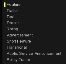
The first parameter to be selected for the composition playlist is the content kind. This phase is important as it tags the composition list with one of the possible kinds (e.g. feature, trailer, rating tag etc).
Title
By default the title of the DCP composition playlist is the one of the current composition in MIST, or the name of the DCP if the source is a DCP. There is no specific restriction on the title of a composition; however in practice the use of this parameter shall be constrained.
|
Special characters and accents not allowed ! The text displayed for the title of a DCI compliant DCP must not contain any special characters or characters with accent marks like: é,”*ç% etc… Accents, symbols and special characters will cause the DCP to fail at ingest into a DCI compliant server. No accented alpha-numerical characters along with periods, hyphens and underscore symbols are allowed however. Due to the fact that it is not clear at this time as to what all the restrictions are between the various manufacturers of DCI compliant servers based on various operating systems (i.e. Linux, Windows) it is highly recommended to only use the standard occidental alphabet and numbers when entering information into the text fields of a DCP. |
As explained earlier, a DCP may contain multiple composition playlists. Once a DCP is ingested into the digital cinema server, it can be split into individual compositions. Each of its compositions may then be scheduled for playout independently. As the number of composition playlists in a server tends to grow quite rapidly, it is good practice to not just type in any old title, but rather use one which has a « standardized » format or pattern. This way, a composition play list will be displayed clearly for the operator and will help him or her to easily identify elements and assemble them into a theater’s playlist.
In order to streamline this practice, a standardized naming convention has been proposed and used by the various DCI authorities. The specifications for this convention can be found here:
This convention allows operators to build standardized names that not only include the name of the composition playlist but also give some important hints about its contents and format.
Annotation
The annotation is to be used to make comments about the composition playlist. Typical annotations include warnings or notes that can help the digital cinema server operator.
Issuer
The Issuer is another optional field that can be used to indicate who was responsible for assembling the composition playlist.
Rating Agency
Although being optional, the rating of a composition playlist is highly recommended for areas where rating systems apply.
A composition playlist may have multiple ratings and you should pay attention to this, especially when creating DCPs for foreign countries. Each rating is based on two parameters; the first of these parameters is the rating agency. Such a rating agency is generally a government driven organism that works on the classification of movies distributed in a specific territory. Each rating agency delivers a country-specific rating for a certain class of movie.
The list of rating agencies is populated with respect to the selected distribution territory. When selecting international distribution, all agencies are listed as shown below:

Once an agency is selected, the list of possible ratings is made available in the second parameter: the actual rating:
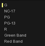
Full Title
The difference between Title and Full Title is that the former may contain technical information, whereas the latter should contain the actual title of the composition. The Full Title field refers to the FullContentTitleText of the CPL.
Release Territory
The next parameter is used to define the distribution territory. Depending on the content or distribution agreements, the territory must be set either on international or a selected country. Failing to properly select the territory will not render the DCP invalid or prevent its transmission.
You can use the mouse wheel to scroll up and down the list to select your territory. Once your territory of distribution is found, click on it and it will be selected.
Please note that not all the countries in the world are listed here. This list is built and updated on a regular basis after the official DCI Naming Convention Territory List. If the country you are looking for is not available, select International as a territory. You can also contact the Digital Cinema Naming Convention organization to have the list updated or contact Marquise Technologies directly via the technical support contact addresses listed in the beginning of the manual.
Chain
This field is to inform about the targeted use for the Composition (a theatre chain, festival screening etc).
Distributor
The Distributor (studio) parameter allows you to select the name of the company that produced the content. The list of companies available in MIST is, like the list of territories, based upon the official Digital Cinema Naming Convention list of studios. If the company you are looking for is not listed, then you may either contact the Digital Cinema Naming Convention organization to have it added, or contact Marquise Technologies directly via the technical support contact addresses listed in the beginning of the manual.
Clicking on the drop-down list and scrolling up and down through the available names, using the mouse wheel, allows you to select the desired studio name:
Facility
The facility parameter is used to define the company that has created the DCP. In other words this is where you should find your company name.
Fox PVID number
Enter the PVID number for a FOX delivery.
20.2.7. Packing List
The Packing List settings are located on the PACKING page of the Export DCP module.
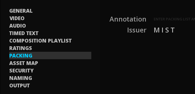
There are two settings in the PACKING page with user text fields that allow you to enter your own indications for reference by the digital cinema server operator.
Annotation
The Annotation text field allows you to add a personalized name as a metadata embedded within the actual Packing List (.PKL). Although this section may not seem noteworthy of further description, there is a particularity with certain DCI servers that will display the Packing List Annotation as the actual name of the DCP composition when displayed by the interface of that server for the operator instead of the actual composition name. For this reason it is crucial to properly name this field with a name that is both easily identifiable by the operator of such a server and congruous with the established DCI naming convention for DCPs.
|
The simplest way to accomplish this is to use the automatically generated name displayed on the Package Name field when you have ticked the option box: Force Naming on the OUTPUT page. This step must be performed as the very last operation just before launching the creation of your DCP because of the nature of the name that is automatically generated when you use the Force Naming option. The Force Naming option updates the abbreviations contained in the name itself with the entry of each new metadata of the DCP you define while preparing your DSM/DCDM for DCI export within MIST. So once everything is properly setup, carefully name your Packing List Annotation as displayed in the Package Name field. |
Issuer
The Issuer text field is a simple metadata which is embedded in the Packing List permitting to identify the technician or service that created the current DCP’s packing list. You may include any information relative to the creation of your DCP here as you like but it is intended for traceability. There is an identical issuer text field in the composition playlist and the asset map as well.
20.2.8. Asset Map
The Asset Map settings are located on the ASSET MAP page of the Master Delivery panel.
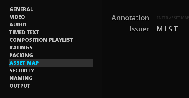
There are two settings in the ASSET MAP page with user text fields that allow you to enter your own indications for reference by the digital cinema server operator.
20.2.9. Security
This page display the settings to be made to encrypt a DCP. For more information on the operation of the DCP encryption, refer to chapter Export an encrypted DCP with MIST.
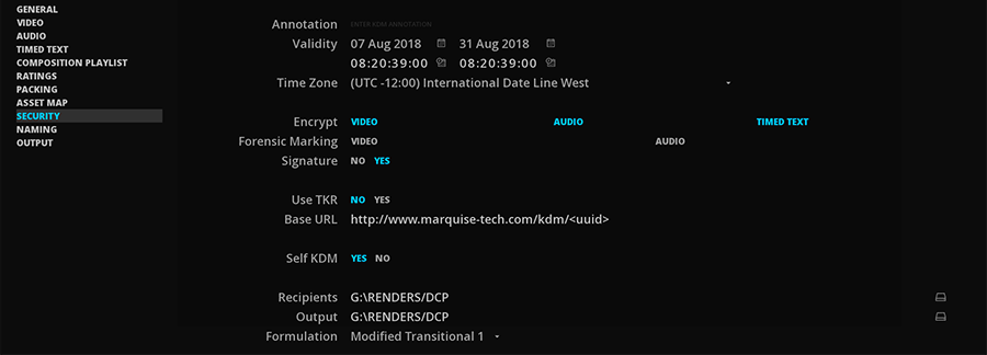
Annotation
The Annotation text field allows you to add a commentary text that will be embedded within all the KDMs, the Certificate Chains and the Self KDMs created for this secure DCP. If used well this Annotation text may be helpful to properly identify KDMs and Certificate Chains or give some other useful information about them in relation to the secure DCP they are created for. You may enter any text you wish here without affecting the contents of your secure DCP or any accompanying KDM and Certificate Chain.
Validity
The validity setting allows you to define a start and end date of the period that your secure DCP will be authorized for screening. Set this parameter carefully in regards to the actual scheduled release date of your secure DCP otherwise you may create a DCP that either will not work on the day it is to be released or stops working before the actual end of its showing time. If you need to modify or extend the showing time of a secure DCP keep in mind you will need to process new KDMs to accommodate the new timings and resend the KDMs to all theatres concerned so that the operators may validate their secure DCP for a new screening period.
The 1st date defines the debut of the valid screening period and the 2nd date defines the end.
-
Click on the calendar icon to select the desired dates of validity:
-
To set the valid hours, clik on the icon next to the hour display (turns cyan) and use the keyboard to change the hour.
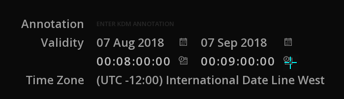
Time Zone
The choice of the Time Zone will make it possible to locate the validity dates chosen previously. It is therefore ideal to situate the Time Zone according to the location of the recipient concerned by the KDM.
Encrypt
This setting allows you to choose which essences you will process with 128 bit AES encryption. You may choose between VIDEO, AUDIO and TIMED TEXT.
Click on one or all of the essence types that you wish to encrypt in your secure DCP. Active encryptions are highlighted in cyan. If no essence is selected, no KDM will be generated because no essence will be encrypted.
|
Remember that only the essences wrapped in an MXF file will be encrypted. For example, if you export a DCP InterOP, the subtitles will not be encrypted despite the selection of this setting. |
Forensic Marking
The forensic Marking setting allows you to choose to activate a forensic marking request bit addressed to the to the D-Cinema server to activate picture and/or sound track watermarking. This forensic marking setting does not modify the picture or sound content processed by MIST in the secure DCP in any way and is only a metadata value included in the CPL that indicates that this content is eligible for forensic watermarking. The DCI does not currently require that DCinema servers systematically provide for watermarking.
Click on the desired essence to active the forensic marking. Selected essences are highlighted in cyan.
Signature
The signature button allows you to choose to digitally sign the DCP you are creating. Please note that all secure DCPs must be digitally signed. The digital signature in required in order to validate the RSA decryption of the AES keys which protect the essences. For this reason all secure DCPs are automatically signed whether you chose to do so or not with this setting as a fail-safe. So this setting actually only allows you to choose whether to digitally sign non-secure DCPs or not.
Use TKR
Nowadays, most KDMs are "zipped" and sent by email. The advantage offered by the Theater Key Retrieval (TKR) are the following:
-
The possibility of an automated system.
-
Secure against the virus and external interventions.
-
Free and at no cost.
-
Quick and easy in obtaining new keys.
-
Allows a transition with the old delivery method of KDM by email.
This system is recent and not widely use yet. However, it is a part of the coming DCI specifications.
The KDM facility has a "hidden" website (impossible to guess because of the UUID number of the CPL) where the KDM is sent. If you need to create new KDMs, you just need to post them. This website address is included inside the CPL of the DCP. When getting the DCP, the connected theater will retrieve the address inside the CPL and will be able to get the KDMs to this website.
The TKR system works for SMPTE and InterOp packages.
Base URL
This is where you must enter the KDM’s address which will be embedded in the CPL when using TKR. By default, the server is that of Marquise Technologies.
The address ending with <uuid> means that the generated address will end with the Universally Unique IDentifier of the CPL that will be generated when exporting the DCP.
Self KDM
The Self KDM button allows you to choose whether to create a KDM that will allow you to reopen and decrypt a secure DCP that was created on your MIST DCI mastering workstation by the very same MIST workstation. This is generally a good idea for the sake of quality control and repurposing of encrypted DCPs you may be commissioned to create. If you choose not to create a self KDM then the encrypted contents of your secure DCP will not be reusable at a later time by your MIST DCI mastering station.
To facilitate the process of reopening secure DCPs that are created on your MIST DCI mastering station we automatically write all Self KDMs to the DKDM subfolder in you system where all KDMs must be located for decryption of secure DCPs.
The following address shows where the DKDM folder is located in a MIST DCI mastering station:
C:\Users\your_login_name_here\AppData\Roaming\MarquiseTechnologies\dkdm
|
The secure DCP import procedure and the proper placement KDMs for decryption of secure DCPs is explained in the section DCP Import. |
Recipients
The Recipients folder is where you choose the location of the public keys of the DCI decoding devices for which you are to create secure DCPs and their respective KDMs for. You must place the public keys (contained within their certificates, as describe earlier in this chapter) of each D-Cinema player that you wish to create a KDM for in this folder.
-
Create a Recipients folder (as described in Export an encrypted DCP with MIST chapter).
-
Copy your public key certificates to this folder using Windows®.
-
Use the BROWSE icon to open the pop-up Browser and navigate to your newly created Recipients folder:
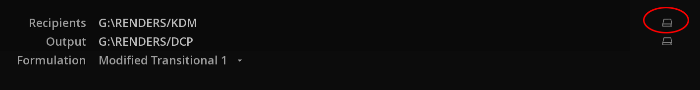
-
Click on the folder to select it and click on OK to validate your selection and close the Browser.
Output
The Output folder is where the KDMs generated for the D-Cinema servers to accompany the secure DCP you are creating will be placed. As described in the first section of this chapter you need to create a folder to designate as the KDM output folder in much the same way you just created the Recipients folder.
-
Create a KDM Output Folder (as described in Export an encrypted DCP with MIST chapter).
-
Use the Output BROWSE icon to open the pop-up Browser and navigate to your newly created Output folder.
-
Click on the folder to select it and click on OK to validate your selection and close the Browser.
|
When the progress bar of the DCP export process reaches 99% it will then begin processing all the KDMs corresponding to the public key certificates present in the Recipients folder. This will take some time so do not cancel the process prematurely by clicking on STOP in the OUTPUT page. Allow MIST ample time to process and encrypt each KDM. You may want to monitor progress of the KDM creation by opening the designated Output folder in a separate Explorer window to see the KDMs being written to disk one-by-one. When all KDMs are written the export process is complete and the Output page shows Make DCP once again instead of STOP. You may now safely deliver copies of your secure DCP and the corresponding KDMs to their respective D-Cinema operators for ingest and decryption. |
Formulations
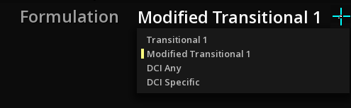
The generated KDMs can be created by MIST in four different formulations:
| Transitional 1 |
This formulation is DEPRECATED and WILL NOT WORK on DCI compliant systems. ONLY FOR InterOp package. |
| Modified Transitional 1 |
A widespread formulation that allows the technological transition between SMPTE and InterOp packages. |
| DCI Any |
A "DCI any" KDM is for single remote SPB (or single projector SPB) setup only. ONLY FOR SMPTE package. |
| DCI Specific |
A "DCI specific" KDM is for single or for multiple remote SPB (or projector SPB) setup. ONLY FOR SMPTE package. |
20.2.10. Naming
When creating a DCP, you can use the tag $ISDCF$ to the tracks' name, to automatically rename your package according to the established Digital Cinema Naming Convention which provides a complete nomenclature definition for use by DCP mastering workstations and their operators.
This convention provides an exhaustive list of all the metadata criteria pertinent to the proper identification of the contents a DCP represented by standardized abbreviations that compose the actual name of the DCP. These abbreviations are displayed in a uniform order separated by underscore characters and composed of otherwise standard occidental alpha-numeric characters, periods and hyphens.
It is also possible to create a cistome name for the D(KDM).
20.2.11. Output Settings
The OUTPUT page allows you to finalize the export settings.
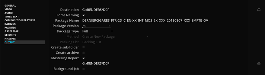
Destination
If the DCP you are creating is an Original Version then you must choose the output destination folder here by using the BROWSE icon to the right of the Destination text field. The System browser appears as pictured below:
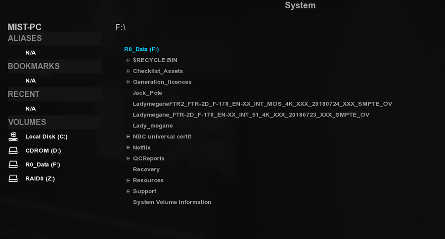
Navigate to the sub folder in your system or over your Network where you wish to create your DCP.
-
Click on OK to validate your choice and close the browser.
|
The Version File must be placed in the same file folder as the Original File version IF you intend to create a single DCP containing ALL elements of a multi-CPL DCP in a single file system folder. Once the multi-CPL DCP is ingested into a DCI compliant playout server, the individual versions may be programmed separately for individual playout as if they were delivered as self-contained DCPs. |
Package Name
You cannot change the package name here. It is a preview based on the name given in the GENERAL page or on the Force Naming option if checked.
Package Version
Increments the version number in the Force Naming convention when creating supplemental version.
Package Type
Allows you to choose the type of package you want to encode:
-
Full
-
Differential (also called Supplemental)
-
Encode and Relink
For more information on this topic, go to the chapter Creating Supplemental DCP.
Method
The method drop-down menu is relative to the type of package chosen. You can:
-
Create a new package.
-
Update Package and New Packing List.
-
Update Package and Update Packing List.
For more information on this topic, go to the chapter Creating Supplemental DCP.
Create sub-folder
This option allows you to generate a subfolder in which MIST will place assets as well as the PKL and the CPL.
This allows in particular in case of multi-version DCP, to separate each version and its assets in its folder while maintaining an Assetmap and Volindex common to the root of the main folder.
Create archive
If Create Archive is selected, an second DCP is archived into a .zip file in addition to the standard DCP package. No compression is applied on the archive.
Make DCP
When all of the steps described in the previous sections of this Export DCP chapter have been completed then you are ready to launch the export of your DCP by clicking the MAKE button.
Once you click on the button MAKE some Status, Performance and Est. (estimated) Time indicators show the progress of your export.
While the DCP is being processed we can see the progress bar cycle through a process pass for each DCP reel. This means that it is processing and wrapping a separate .mxf essence file per reel and including them in the current multi-reel DCP.
The Status indicator shows the frame currently being encoded, the total number of frames to encode and the progress in the form of a percentage counter and a blue progress bar.
The Performance indicator shows the average number of frames being encoded into JPEG2000 per second. As mentioned previously performance of the system may be greatly impacted by the choice of GPU and high performance media volumes.
When the last frame of JPEG 2000 is encoded the finalization process of the DCP begins so do not be alarmed when the progress bar reaches 99% and seems to stay stall. It is in fact wrapping the media essences into .MXF containers and subsequently tallying up all the hashes and checksums of each element within the DCP and appending them as metadata within the elements themselves. These checksums are examined stored and compared to the actual checksums and hashes present in the DCP by the DCI compliant server at the moment of ingest into the server. They are also used in the encryption process to properly validate the actual contents of the DCP, including encrypted elements, in order to prevent unauthorized replacement of any element of the DCP that would compromise its contents. This integrity check is performed at each ingest of a DCP into a DCI compliant server.
|
No user modifications may be performed on the contents of a DCP after the Mastering process has been performed. Doing so will result in a corrupted DCP that will be systematically refused by any and all DCI compliant servers. |
20.3. Importing a DCP
Importing a DCP into a Project is similar to the process of ingesting a DCP into a DCI compliant server. Each DCP has at least one composition playlist (CPL) for the original version and possibly a number of sub versions, each with its own CPL.
Once the DCP is imported within a project, all the elements in the timeline are ready for screening, quality control, etc.
20.3.1. Drag & Drop a DCP
Refer to chapter Media Import Drag & Drop
20.4. Importing an encrypted DCP
When a DPC is encrypted, the first step is to import the package.
Then proceed to the import of the KDM itself, using IMPORT from the bottom menu.
→ Browse directories, select the KDM and click OK.
|
You can filter your search by selecting the type of file: 
|
20.5. DCP Encryption
20.5.1. Definitions
What is a DCI key?
An encryption key is simply a series of letters and numbers (an alphanumeric string) that is used to determine the output of a cryptographic algorithm. The cryptographic algorithm uses the key to encrypt a chunk of data that needs to be protected from illicit use or modification. This chunk of data can be virtually anything from a single bit of data to the entire contents of a vast library archive.
Inversely a key is also used to decrypt a chunk of data that was previously encrypted with the same cryptographic algorithm.
There are two types of keys used for security encryption and decryption within the DCI security scheme:
Symmetric Key
A single alphanumeric string key that is used both for encrypting and decrypting with a 128 bit AES cryptographic algorithm:
-
128 bit AES encryption is used to encode the video, audio and subtitle essences.
-
The same randomly generated key is used both to encode and decode them.
Asymmetric Keys
Two unique alphanumeric string keys that form a pair used in the process of encrypting and decrypting with a 2048 bit RSA cryptographic algorithm.
- One Public Key to encrypt
-
Created uniquely for a DCI compliant decoding device by the manufacturer (DCI playout server or DCI mastering workstation). It is a key that is made publically available for use by DCI Mastering workstations to encode a secure DCP that may only be decoded by the DCI compliant decoding device from which the public key originated.
- One Private Key to decrypt
-
Created uniquely for a DCI compliant decoding device by the manufacturer. As its name implies, the Private Key is “hidden” within the DCI compliant decoding device’s file system and password protected. It is used solely to authorize the cryptographic algorithm present in the DCI compliant decoding device to decrypt files that were created with the Public Key of the device itself. The private key is compared with the returned public key present in the Key Delivery Message (KDM) at the moment of ingest of the DCP into the DCI compliant decoding device. Once the cryptographic algorithm successfully determines that the two RSA keys coincide as a pair and that the signed source is valid in relation to the signed essences within the secure DCP then the decryption process is validated and the combined keys are used to decipher the AES keys that protect the encrypted essences of the secure DCP.
Once the AES keys are decrypted then the Integrated Media Block (IMB) of the D-Cinema player can decrypt the actual essences for real-time screening of the secure DCP. All essence decryption is handled in real-time in the IMB in order to avoid writing a decoded copy to the internal storage of the D-Cinema player, thus avoiding a huge security breach. The essences are decoded and played out directly from the IMB (typically located within the actual projector’s chassis) to the projector’s optical display array and the audio amplification chain without any intermediate access to the decoded digital video signal.
What is a DCI Certificate?
A DCI certificate is a .cer or .pem file originating from a DCI compliant decoding device. It contains a digital signature and the RSA Public Key of the DCI decoding device. This certificate file is the accepted method for delivering the RSA Public Key of a DCI decoding device to a DCI mastering workstation for creation of a secure DCP.
The MIST DCI mastering station installation creates its own self-signed certificate containing the Public Key needed to create a secure DCP by any MIST DCI mastering station or a 3rd party DCI mastering station. The 3rd party DCI mastering station may use the certificate containing the public key of the MIST DCI mastering station to encrypt a DCP and create a KDM (Key Delivery Message). The KDM must then be copied to the MIST DCI mastering station in the DKDM folder to decrypt the secure DCP for import, screening, quality control, versioning, additional KDM creation and DCP re-mastering. In this way you may exchange secure DCP content with operators of another MIST DCI mastering station or a 3rd party DCI Mastering station.
What is a Digital Signature?
The digital signature within the certificate helps ensure the validity of the origin of the certificate itself by giving a reference as to the unique identity of the DCI Mastering workstation for which the certificate was created. The signature may either be self-signed by the DCI Mastering workstation software or created by an independent certificate authority (CA), although independent certification involves more effort on the behalf of the issuer than a self-signed certificate it allows for a direct online verification from the CA service in most cases instead of having to manually request a certificate duplicate from the issuer, as is the case with self-signed certificates.
What is a Certificate chain?
A certificate may include an entire chain of certificate signatures with referrals to higher and higher authorities, each parent vouching for the authenticity of its descendants from top to bottom of the chain in order to validate the singular identity of the final issuer of the certificate, for the sake of security and traceability. The terminology of these hierarchical rank levels of the chain is expressed as follows from top to bottom:
Root certificate
-
Is the singular parent source certificate of the chain.
-
Includes a public key and self-signed signature encapsulated in an XML file.
-
Has with either an
.xml,.pemor a.cerfile extension. -
Is used to sign and create intermediate or leaf certificates.
-
Is associated with a root private key that is encrypted, password protected and encapsulated in an XML file labeled:
mist.pkin the certificates folder of MIST. -
Defines the maximum number of rank levels from the root to the final leaf certificate in the chain.
-
Is the only certificate that needs to be verified via a secure communication channel to the creator in order to validate the whole certificate chain.
Intermediate certificate
-
There may be many ranks of intermediate certificates between the root and the final leaves in a certificate chain, as defined by the root certificate.
-
Is signed by its direct parent certificate (which may be the root certificate or an intermediate certificate that is higher in rank).
-
Includes a public key, used to sign and create other intermediate certificates or the final leaf certificates, which is typically encapsulated in an
.xml,.pemor a.cerfile . -
Is associated with its own intermediate private key that is encrypted and password protected. It must be available to verify the validity of the whole chain back to the root.
Leaf certificate
-
Is the final end rank in a certificate chain.
-
Is signed by its direct parent certificate (which may be the root certificate or an intermediate certificate).
-
Includes the public key which is typically encapsulated in an
.xml,.pemor a.cerfile. -
Is associated with its own leaf private key that is encrypted, password protected and encapsulated in an XML file labeled:
mist.pkin the certificates folder of MIST. -
May not be used to create other intermediate certificates or leaf certificates.
-
Must be available to verify the validity of the whole chain back to the root.
-
Is used by the MIST DCI mastering station or D-Cinema decoding device (or other third party DCI mastering software) to provide digital signature certification and the public key needed to create a secure DCP for that given machine through the designated
.pemor.cerfile that is to be delivered to the Mastering station operator.
Levels of encryption in a secure DCP
As stated above a DCI decoding device’s certificate must be delivered to the MIST DCI mastering workstation in order to create an encrypted DCP. First a random AES encryption key is created by MIST to encrypt the .mxf essences with a 128 bit AES encryption algorithm. Then the RSA Public Key is extracted from the DCI decoding device’s certificate by MIST and used to encrypt the AES keys. Then finally the CPL, PKL and KDM are signed using MIST’s Private RSA Key.
So when MIST is described as using the Public Key of an asymmetric RSA key pair to encrypt a DCP, what it is actually encrypting is the symmetric AES password keys and not the essences themselves. The RSA encrypted AES keys are written then to the KDM (KDM explained below). The composition playlist (CPL), KDM and the Packing List (PKL) are then signed with the Private Key of the MIST DCI mastering station and are placed in the DCP file system folder along with the encrypted essences and the remaining .xml type reference files.
-
The 1st level of encryption security is the 128 bit AES encryption of each .mxf essence which produces one AES key per essence.
-
The 2nd level is the 2048 bit RSA encryption of the AES keys using the Public Key extracted from the certificate of the D-Cinema player.
-
The 3rd level is the 2048 bit RSA encryption applied to the digital signature embedded in the CPL, KDM and the PKL of the DCP using the RSA key of the MIST DCI mastering station.
|
Keep in mind that RSA encryption works with a pair of keys: the RSA public key is used to encrypt the AES keys and digital signatures while the RSA private key is used to decrypt them. |
What is a KDM ?
KDM stand for Key Delivery Message. The KDM is an .xml file generated by the DCI mastering workstation at the moment of encryption of a DCP version which contains rather a key, more a collection of elements including the keys and signatures.
The KDM’s function is to allow the D-Cinema player to decrypt the video, sound and subtitle essences of a secure DCP. Each KDM contains the decryption key of a specific CPL (composition playlist) so if you are delivering a DCP with multiple secure versions then you will also need to generate and deliver a separate and unique KDM for each secure version because they each have their own CPL.
In an industrial distribution environment the KDM is usually delivered separately from the DCP itself due to the potentially large quantities of KDMs that may be created to accommodate all the D-Cinema players designated for the screening of a widely distributed feature release. It is most commonly a zipped file attached to an e-mail designated to the DCI decoding device operator or as a zipped file made available for download from an FTP server. In any case, any delivery method is acceptable as long as the KDM itself is not corrupted in the process.
|
Due to the highly sensitive nature of |
What is a Self KDM ?
A self KDM is a KDM for use by the Mastering station to open its own encrypted DCPs. It may optionally be created by a MIST DCI Mastering station at the moment of creation of a secure DCP. It uses the same process to be created as a regular distribution KDM except that it uses the public key of MIST itself to encrypt the AES keys stored in the self KDM instead of the public key of another DCI decoder.
20.5.2. Synthesis of the security elements of the DCI Mastering process
AES key
-
Symmetric, 128bit.
-
Used to encrypt/decrypt audio/video/subtitles track files.
-
One key per track.
-
MIST automatically generates random AES keys, which are not visible to the user.
Encryption Key
-
Asymmetric key pair using the RSA cryptographic algorithm.
-
Used to encrypt/decrypt the AES keys.
-
By the manufacturer of the DCI player and issued to the owner of the DCI decoding device.
-
Key pair consists of the Public and Private keys.
-
The public key is used to encrypt the AES keys stored in the KDM of a secure DCP.
-
Is embedded in the DCI decoding device’s certificate.
-
May be freely distributed.
-
Private key is stored securely on the DCI decoding device and is used to decrypt the AES keys stored in the KDM of a secure DCP.
-
Should never be distributed to anyone at any time (serious security breach that is traceable to the owner of the DCI mastering station).
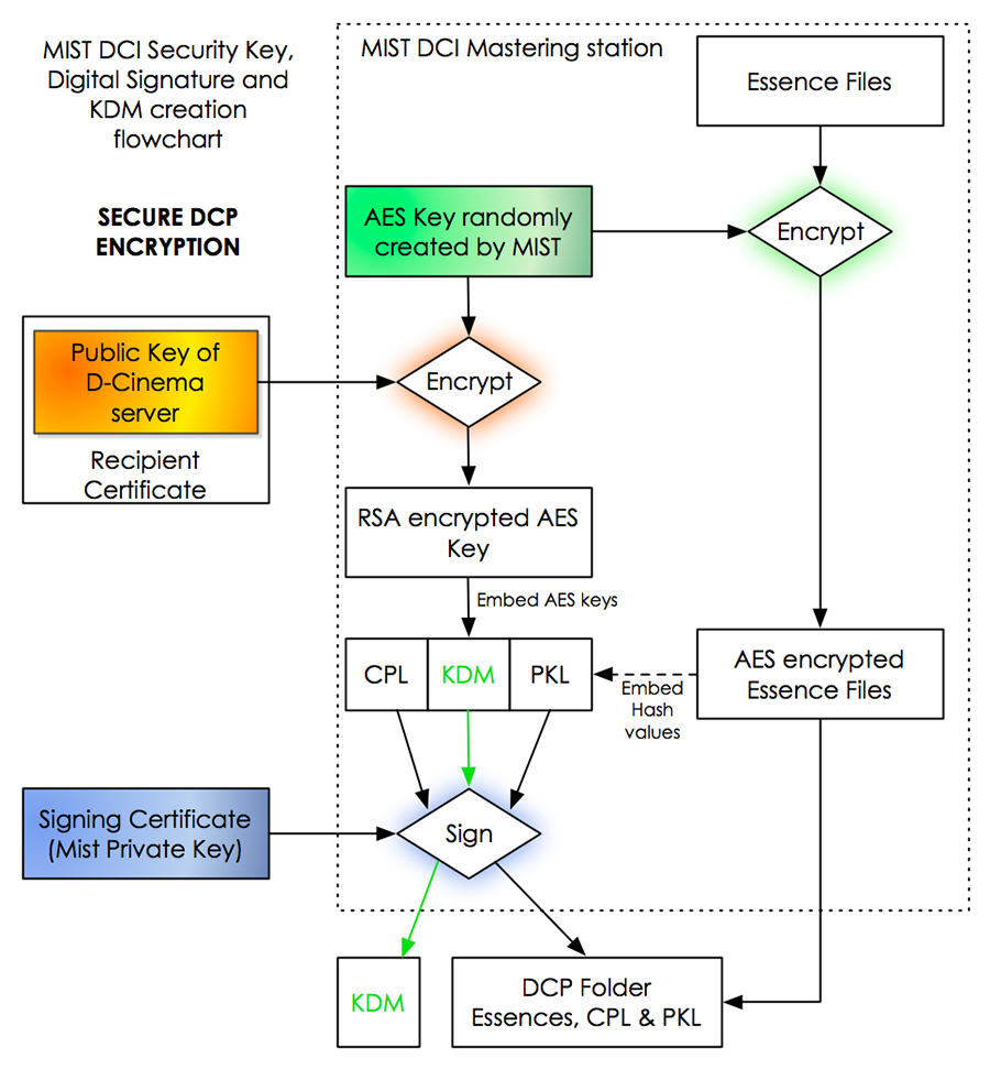
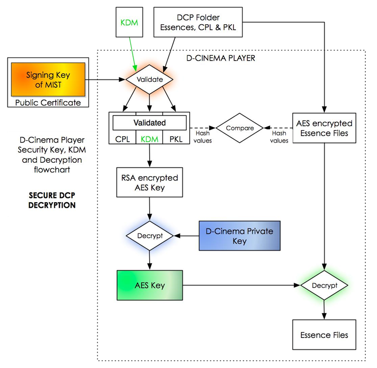
20.5.3. Where to find…
Public Certificate containing its Public Key and Digital Signature
- Name
-
MIST.cert.sha256.crt
- Location
-
C:\ProgramData\Marquise Technologies\MIST\certificates
- Purpose
-
This file contains MIST’s public key and digital signature. It must to be sent to any DCI mastering station that needs to create a secure DCP for use by MIST. This also includes MIST itself. It is used to encrypt the AES keys of an outgoing secure DCP at the moment of its creation.
Public Certificate Chain
- Name
-
MIST.chain.sha256.pem
- Location
-
C:\ProgramData\Marquise Technologies\MIST\certificates
- Purpose
-
This file contains the entire certificate chain of digital signatures of the MIST DCI mastering station. It is required if the certificate needs to be verified. It may be distributed freely in accompaniment with the Public Leaf Certificate.
.pem= Privacy-enhanced Electronic Mail.
Private Key Location in MIST
- Name
-
MIST.pk
- Location
-
C:\ProgramData\Marquise Technologies\MIST\certificates
- Purpose
-
This file is strictly confidential and should NEVER be distributed and remain in the MIST DCI mastering station. It is used to sign and encrypt outgoing RSA encrypted AES keys and DCP
.xmlfiles (CPL, PKL & KDM) at the moment of creation of a secure DCP. It is also used to decrypt the incoming RSA encrypted AES keys at the moment of import of a secure DCP.
KDM .xml Location in MIST
- Name
-
k_MIST.cert.sha256.xml
- Location
-
You choose this output folder in the Security page of the MIST DCP export tool.
- Purpose
-
This file contains the authenticated public key of MIST, the authenticated private key reference of the DCI decoding device and digital signature of MIST. It is used to validate and decrypt the RSA encrypted and signed
.xmlfiles as well as decode the RSA encoded AES keys of its secure DCP.
Self KDM Location in MIST
- Name
-
name_of_the_DCP_here.kdm.xml
- Location
-
C:\ProgramData\Marquise Technologies\MIST\dkdm\mist
- Purpose
-
This file contains the authenticated public key, authenticated private key reference and digital signature of the MIST DCI mastering station itself. It is used to validate and decrypt the RSA encrypted and signed
.xmlfiles as well as decode the RSA encoded AES keys of its secure DCP.
Certificate Chain .xml Location in MIST
- Name
-
k_MIST.chain.sha256.xml
- Location
-
You choose this output folder in the Security page of the MIST DCP export tool.
- Purpose
-
This file enables the DCI decoding device that will mount the secure DCP to verify the whole certification chain of the digital signature of the KDM originating from the MIST DCI mastering station in order to validate its decryption.
Public certificates of DCI compliant servers in the world
- Qube
- Doremi
-
ftp.doremilabs.com
user: service password: t3chn1c1an
The certificates are located in the Certificates directory.
- Dolby
-
Send email to dolbycerts@dolby.com
20.5.4. Export an encrypted DCP with MIST
In this section you will see a step-by-step walk-thorough of how to create a secure DCP with the Master Delivery as described in the Digital Cinema Package Export Tool section.
If you simply want to create a new KDM on an existing encrypted DCP, it is advisable to build it from the existing KeyMaster account. Create a DKDM from MIST and then duplicate the KDM for new deliveries on demand through KeyMaster. KeyMaster can duplicate KDMs without having to use the DCP while MIST creates new KDMs only when creating new DCP packages.
Before you begin to set up your parameters in the Master Delivery for the creation of a secure DCP you must verify that you have access the following files:
-
Public Certificate (
.pemor.crt) of the DCI decoding device you wish to create your secure DCP for. -
Certificate Chain (
.pemor.xml) if available of the DCI decoding device you wish to create your secure DCP for.
|
The public certificate and the certificate chain may either be provided by the manufacturer of the DCI decoding device (see website references at the end of this section), by a qualified operator of the DCI decoding device capable of access and delivering it securely or by the DCI management service of the content provider that has commissioned the creation of the secure DCP you are to create. |
Step 1: Copy the Public Certificate
You must copy the public certificate (and the certificate chain, if available) of the DCI decoding device to an internal folder in your MIST DCI Mastering station that you will later designate as the Recipients folder by MIST in order to properly sign your secure DCP and create a KDM capable of validating it for that DCI decoding device. Each public certificate is an .xml style text file (regardless of its file extension) that has a unique name issued by the manufacturer.
For this reason you may process as many public certificates as you wish in a single DCP export pass by designating a single folder containing the certificates for all the DCI decoding devices that will screen your secure DCP.
For simplicity’s sake however this example will only be dealing with a single public certificate and certificate chain to create a single secure DCP and its subsequent KDM.
Step 2
Create the Recipients folder anywhere on your system and name it in a way that makes sense for you to easily associate it with the secure DCP you are creating.
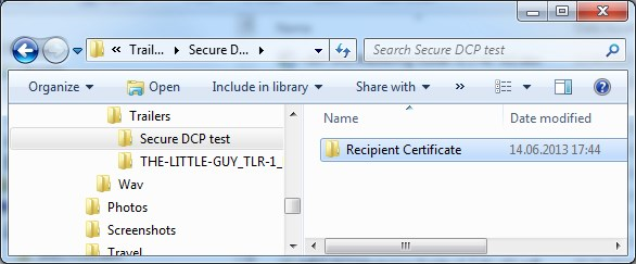
Step 3
Copy the public certificate and the certificate chain (if available) to this new folder.
The example public certificate and certificate chain pictured below were issued by DoReMi® for one of their D-Cinema players. They were downloaded from their public FTP server. DoReMi and other D-Cinema server manufacturers issue a serial number identifier to each D-Cinema player as per the DCI regulations on security. So if you can determine the serial number of the D-Cinema player you can obtain a copy of its public key from their website FTP (listed at the end of this section).
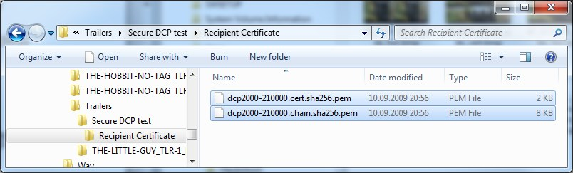
Step 4
Now create the Output KDM folder where MIST will process the KDM of your secure DPC that you are creating. Like the Recipients folder you will designate this folder by MIST in the Security page of the Master Delivery.
It may be a good idea to keep it in the same folder as the Recipients folder for the sake of organization but you may put this Output KDM folder anywhere you like in your system. Just make sure not to mix KDMs for separate DCPs by designating the same folder for two completely different secure DCPs.
Step 5
Finalize the export as described in chapter Exporting a DCP, and display the SECURITY page to setup your KDM settings :
20.6. Creating Supplemental DCP
This section explains how to create a supplemental version file with MIST.
20.6.1. About DCP versioning
On occasion it is necessary to create multi-version DCPs for distribution with similar contents but minor changes. Such changes could be related to a single element that is different while other elements remain exactly the same.
The file system structure of DCPs makes it possible to simply replace and append essences within a DCP while creating new CPLs (composition playlists) that take those changes into account.
What is a Version File ?
A single digital cinema package can be composed of one or more composition playlists. Each of these composition playlists can have different scopes and therefore potentially different parameters. Each additional composition playlist is referred to as a “Version File” (VF). Each version shares or excludes assets contained within the DCP essentially saving storage space, reducing ingest times and simplifying final delivery of encoded material by combining versions into a single DCP.
The process of creating a supplemental version in an existing DCP is called a Version File and its creation involves:
-
Loading a composition into MIST, which presumably originated from the existing DCP that you wish to modify by adding an additional version to.
-
Changing the content by either adding, subtracting or replacing essences within the MIST timeline.
-
Re-exporting these changes as a Version File back into the original DCP.
This newly created version is embedded within the DCP itself and to the eyes of the projection operator, allows the choice between all embedded versions within for playout without having to re-ingest all the shared essences. The DCP simply shares common essences between versions, instead of making copies, while also containing non-shared essences. So if an original DCP CPL (Original Version) uses the same picture content as its supplemental version file then both versions will use the same source picture for playout.
MIST offers 3 different methods to create a Supplemental DCP:
-
Full
-
Differential
-
Encode & Relink
20.6.2. The Differential method
The differential method creates a version file that contains only the asset that are different from the original version, and adds references to the assets of the original versions.
Prepare the timeline for Versioning
As explained previously, it is necessary for an additional version to be linked to an original version. To do this, import your OV DCP and apply your changes from the CPL you want to modify.
If you have to modify reels in and out points for the supplemental version, this will not involve any encoding process. Because the asset is the same, only the in and out points change.
In the general settings of the composition, make sure you are in VERSIONING mode. When you import a DCP, MIST automatically switches to that mode.
Export a Supplemental version
From the Master Delivery Panel select Digital Cinema Package and set or update the settings, especially those related to the assets you are editing. For example, if you only add audio assets and have not added or edited video, you do not need to dwell on the video settings.
Perform the following steps:
-
Rename your package from the GENERAL page.
-
From the COMPOSITION PLAYLIST page, update your annotations if necessary, but above all it is advisable to rename what will become the name of your CPL from the Title text field.
-
Update PACKING and ASSETMAP page.
-
Go to the SECURITY page to setup an optional encryption.
-
From the NAMING page, rename the supplemental version assets to distinguish them from the original version. This can be very useful especially when the DCP has multiple CPLs with many assets. To save time, rename only the assets that will be generated.
-
From the OUTPUT page, there are differents ways to export a supplemental version.
Package Version number

This setting is a value slider and must be incremented every time you wish to create an additional Version File. So after you have created Version File N°1 and you are ready to embed a new Version File into your Original Version click and drag the slider to N°2 and launch the export. Repeat this process of incrementing the slider for all additional Version Files you wish to create.
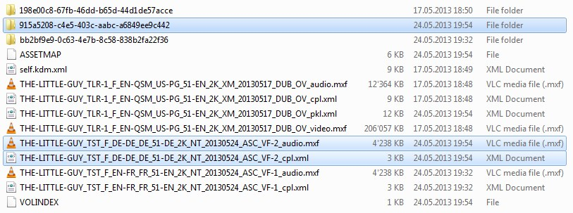
Notice now that by incrementing the Version File number slider setting from N°1 for the first example to N°2 for the second example that instead of overwriting the CLP, audio and subtitle essences of the first Version File example, we have created a new CPL, audio and subtitle essences for the second Version File example (highlighted in the screenshot above).
Export to a new folder
It is possible to export the DCP as a complete package. This means that your DCP will always be linked to its original version but may be packaged as an independent folder not placed in the root folder of the OV version:
-
VOLINDEX
-
ASSETMAP
-
PACKING LIST
-
CPL
-
New assets
In order to do this, from the Destination browser, select a path which is not the one of the OV DCP:
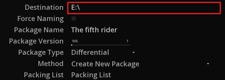
Select the package type from the drop-down menu by choosing * Differential * (aka supplemental). Because we have not designated the OV DCP as a destination, the choice of method and packing list is not available to us.
Export to OV DCP root folder
If you want to export the supplemental version in the same folder as our OV DCP, just point to the root destination of our package:
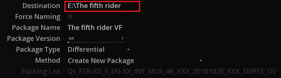
Select the Differential type like previous explanations.
By the use of this method, three choices are available to you:
| Create new package |
a full package will be created inside a new folder. |
| Update package and new packing list |
will update the package at its root by adding new assets, a new CPL of this modified composition and a new packing list (so the one of the OV is kept). |
| Update package and update packing list |
will update the package at its root by adding new assets and a new CPL. No more files will be created. |
|
If you choose the Update package and update packing list method, the Packing list drop-down menu is accessible and you can select in case of several packing list, the one to update. |
The choice of method may vary according to needs and requests.
|
The "Update package and update packing list" method can be dangerous if you need for any reason to go back because the packing list has been updated and in case of undesirable modification, you will have to regenerate it taking into account the other versions listed in it. |
Once you have chosen all the parameters and filled in the metadata fields on each page of the Master Delivery required to properly identify all elements in your DCP Version File you are ready to begin the export process by clicking on MAKE DCP.
During the Version File export MIST creates three temporary folders to process the essences from their native DSM state to a temporary DCDM state in those folders and then finally wraps the individual essences to .MXF containers. These three temporary folders are automatically erased once the final .MXF encapsulated essences are created and the DCP is finalized at the very end of the export process.
The progress bar will appear showing an estimation of the time remaining to process your DCP. Allow this cycle to complete until the status shows “Ready…” once more and click the EXIT button or push the Escape key on your PC keyboard to return to your Composition.
|
It is worth noting that you must take special care not to mix DCI standards when creating a Version File. If your Original Version is was created as an Interop DCP then your Version File should not be in SMPTE mode or include SMPTE subtitles and vice versa. The resulting DCP may or may not be properly encoded and reusable by MIST upon import but there is no way of predicting how it would be interpreted by each and every DCI compliant server model in use today. The most likely result would be that it would be rejected at ingest and simply cause problems so avoid mixing SMPTE and Interop Versioning for the best trouble-free results. It is highly advised to deliver SMPTE & Interop separately (different DCPs, different hard drives). |
20.6.3. The Encode and Relink method
Encode and Relink mechanism
When using Encode & Relink, the files will be either recreated through copy or hardlinking. No new MXFs are created because the original MXFs are used which means that the UUID of the asset will be not altered. MIST will just recalculate the hash values without re-encoding the files. However new package files like CPL and PKL are created during the process. It does the same packaging type than the Full Package but it’s an instant process. It could be useful as example, if you need to consolidate one CPL from a multiple version.
From the Master Delivery, if you need to update any CPL properties or just renamed assets from the NAMING page, use the encode & relink package type. In that way, you will update your package without the need to re-encode.
-
First, make sure you are in VERSIONING type from the GENERAL settings of the Composition Settings.
-
From the OUTPUT page of the Master Delivery, select a target destination. If you select the same output hard disk than your DCP, MIST will do a hardlink. If not it will copy files.
-
Like differential type, you can use same methods and packing list options if targeting the OV DCP folder.
FAQs & tips for Encode and Relink
Can I create a KDM with Encode and Relink method ?
As explained previously, you can’t create KDM for the imported DCP without encoding. The encode and relink doesn’t work for this purpose. MIST creates new KDMs only when creating new packages. Nevertheless, KeyMaster can duplicate KDMs without having to use the DCP at all.
My asset file exceeds a given size. Can I use the Encode and relink if editing the file ?
The Encode & Relink would not work in this case because the original file will be relinked in full and the unique ID of the asset will be preserved and the cut will only be virtual via the CPL.
In this case, you need to recreate a new full package because you need to have as much new MXFs than edits, the unique IDs need to be regenerated. However the images encoded in the origanl MXF will be simply rewrapped, not re-encoded. Open your DCP, place one or more cuts where needed in the timeline and render a full new package. The video essence will be rewrapped.
Can I use Encode and Relink method with InterOp assets when creating SMPTE DCP ?
As explained along this user manual, mix InterOP and SMPTE is not allowed. An encoding or re-wrapping operation should occur in this case.
Keep the head and tail leaders in the DCP assets without including them in the CPL
To adjust the in and out points for your assets, then:
-
Import your DCP which include head and tail leaders.
-
Make sure the composition is in VERSIONING.
-
Trim the head & tails as required.
-
Output using encode & relink.
If you import your DCP in MIST, you will notice that the composition is using the defined in and out point while maintaining front and end leaders of the MXF file intact.
20.7. Creating Stereo3D DCP
This section will explain how to create a stereoscopic (3D) DCP with the MIST DCI Mastering workstation using dual layer 3D video clips in the composition
20.7.1. Background of Stereo3D DCPs
Stereoscopic DCPs contain two independent video channels; one containing the left eye content and another containing the right eye.
When output through a DCI compliant server capable of displaying 3D material, the two JPEG2000 channels are sent to the decoder head within the DCI compliant projector and decoded in parallel simultaneously.
The type of stereoscopic projection method used in a particular projector may vary from system to system but there are always two JPEG2000 video channels to be decoded in a 3D DCP. This applies to the overall characteristics of a stereoscopic DCP no matter what method is used to display the final image so in regards to the picture, everything is double and requires twice as much storage space, real-time decoding power and server data bit rates from the internal storage to the decoder head for 3D picture to playout smoothly.
20.7.2. 3D display modes in MIST
MIST has truly exhaustive stereoscopic support built-in to its interface and video engine that allows to combine 3D channels in real-time directly from the time line for display in all conceivable display modes, whether for cinema or broadcast, at all resolutions and frame rates up to 4K. It also provides for all possible output combinations to its DVI display monitor and HD-SDI outputs using an Nvidia GPU and an AJA or Bluefish 444 video board.
Setting up MIST for 3D display
In order to begin displaying 3D picture within MIST there are a couple of parameters that must be properly setup first before you may switch the display modes listed in the section following this one.
The first parameter that must be defined is to put the MIST Composition in STEREO mode:
-
While in the Timeline Module, right-click on Viewport to call up the Action Menu.
-
Click on Settings to open the Composition Settings menu.
-
Open the GENERAL page.
-
Click on the appropriate Mode button marked STEREO (3D).
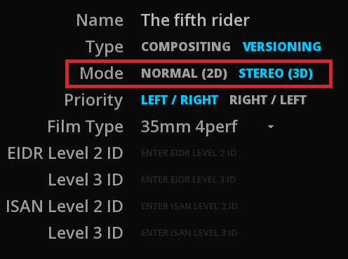
This will activate the 3D engine within MIST and allow the 3D display modes as well as 3D related functions to be active. Now with the Mode set to Stereo, video tracks 1 and 2 are considered to be the left and right channels respectively of a single 3D program.
Incidentally the Priority buttons allow choosing the video track order. By default track 1 is left and track 2 is right (L/R). You may reverse the track order here by choosing Right/Left instead making track 1 right and track 2 left.
Once MIST is in stereo mode you may create two new video tracks in the Timeline with the V+ button and name them as left and right for clarity.
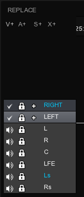
Once you have created the two video tracks you are ready to place the left and right channel clips of a dual file sequence 3D picture from the Library in the timeline. Pick up your first left eye 3D clip and past it into the timeline.
In the example below each clip was picked up individually and pasted to the playhead cursor in the timeline by first clicking on the track itself to select it as the destination track and then typing Ctrl+V to paste the clip into the timeline. Then the process is repeated on the other track for the right eye channel.
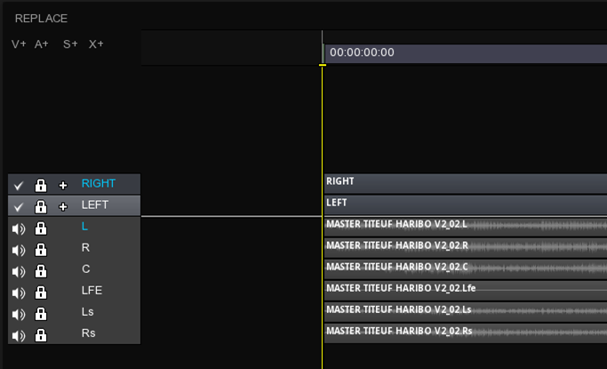
20.7.3. Viewport
In a new composition, only the left video track is displayed on-screen by default. In order to display the other modes press Alt + right-click on the Viewport then go to 2D/3D page.
| Display |
The Display buttons change the channel mode of the 3D to be displayed both on the DVI monitor and to the HD-SDI outputs of the Bluefish board. |
| Stereo |
Stereo buttons (Left, Right, D-MAP, BLEND, DUAL and STEREO) are active only when the Display mode is set to STEREO |
| Kind |
Kind buttons are only active in STEREO mode and they change in relation to the type of stereo mode activated (ANAGLYPH, SIDE-BY-SIDE, INTERLACED and MESH). |
Various modes displayable are summarized below:
Display Left only

Display Right only
Display D-Map

Display Blend
Display Dual
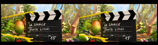
STEREO Anaglyph True
STEREO Anaglyph Grey

STEREO Anaglyph Color
STEREO SIDE-BY-SIDE Horizontal

STEREO SIDE-BY-SIDE Vertical
STEREO INTERLACED HORIZONTAL
STEREO INTERLACED VERTICAL
STEREO INTERLACED MESH 3DMESH (TI)

20.7.4. Merging left and right channels
Once you have setup the Composition’s video engine to stereo mode, placed left and right clips on tracks 1 and 2, verified the synchronization of all video, audio and subtitle channels, chosen the proper 3D display mode for your HD-SDI outputs you are ready for the final crucial step before exporting your 3D DSM Composition as a DCP with the Master Delivery. In the final step, MIST requires that you merge the left and right channels into a single 3D layer clip.
In order to merge the left and right channels into a single 3D layer clip:
-
Open the TimeLine Module.
-
Select track 2 (right eye) by clicking in the track.
-
Press Ctrl+Shift+W to merge the left and right layers together or right click on the track.
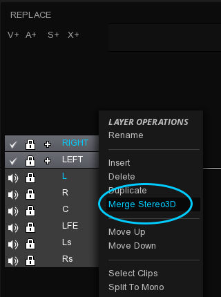
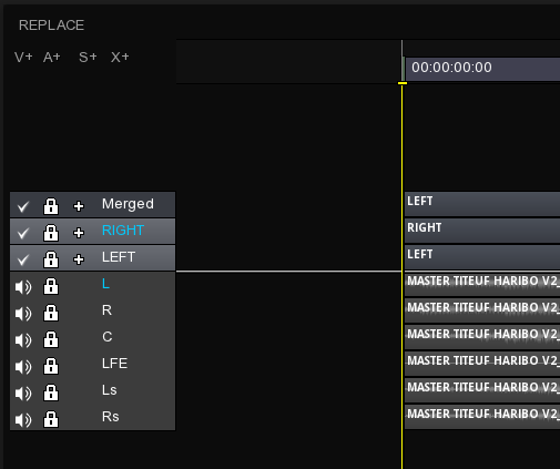
The resulting “Merged” layer clip looks like the screenshot above.
Notice that your originals layers are kept. Once the layers are merged you may no longer adjust the sync between the left channel and the right channels within the merged layer clip because they now act as a single clip.
|
All grading and Pan & Scan functions may still be performed in tandem on both layers at the same time or independently with the Left, Right and Link Stereo buttons in the Grade menu tabs, even though the 3D layer appears to be a single clip. You may also move this merged layer clip in the time line vertically from one track to another or even move it horizontally from one timecode position to another. |
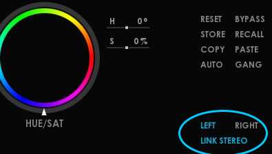
Once you have pre-mastered your stereoscopic DSM, you have performed the merge layer operation and you are satisfied with the overall content of your stereoscopic DSM, you may proceed with the export of your DCP as described in the chapter Digital Cinema Package Export Tool.
20.8. Creating a DCP for FOX
In case of DCP delivery for Fox, you must enter the PVID number for each CPL. The number must be provided to you by Fox International upstream (please refer to the current Fox specifications for more information).
Fox PVID stands for Fox Presentation Version ID and can be embedded in the CPL as a custom Metadata Extension for both SMPTE and InterOp DCP’s format.
-
To do this, enter the PVID number in the appropriate field from the Composition Playlist page of the Master Delivery.
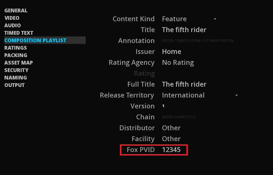
20.9. Creating a DCP Eclair Color
MIST can generate two types of EclairColor DCPs:
-
EclairColor EC1 Extended Dynamic Range (EDR) encoded in XYZ with a P3 DCI white point and a gamma of 2.8 (EclairColor EC1). The maximum luminance is 105 nits.
-
EclairColor EC1 High Dynamic Range (HDR) uses the same parameters as the EDR version but with a maximum luminance level of 350 nits.
When generating these DCPs with MIST, a flag is added to the ExtensionMetadata of the CPL to define the version of DCP EclairColor used.
To export a EclairColor EC1 DCP:
-
Make sure your source content has been mastered for EclairColor EC1 and setup the CMS accordingly. Refer to chapter Color Management for further explanations. If using MTCMS system, don’t forget to define the maximum luminance levels.
-
From the GENERAL page of the Master Delivery, choose SMPTE format.
-
From the VIDEO page, select the desired output Color space from the dedicated drop-down menu: EclairColor EC1 EDR or EclairColor EC1 HDR.
-
According to the previous step, define the Peak Luminance at 105 nits or 350 nits. The Screen Luminance value is up to your discretion.
After configuring the rest of your DCP settings, you can export your DCP.
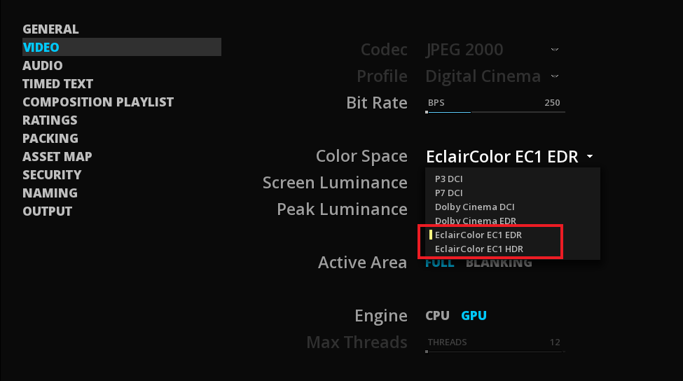
20.10. Creating a DCP Dolby Cinema
MIST can generate two types of Dolby Cinema DCPs:
-
Dolby Cinema DCI encoded in XYZ with a P3 DCI white point and a gamma of 2.6. The maximum luminance is 52.37 nits.
-
Dolby Cinema EDR encoded in XYZ with a P3 D65 white point and using a PQ curve. The maximum luminance is 108 nits.
When generating these DCPs with MIST, a mandatory flag for Dolby Cinema playback is added to the ExtensionMetadata of the CPL.
To export a Dolby Cinema DCP:
-
Make sure your source content has been mastered for Dolby Cinema and setup the CMS accordingly. Refer to chapter Color Management for further explanations. If using MTCMS system, don’t forget to define the maximum luminance levels.
-
From the GENERAL page of the Master Delivery, choose SMPTE format.
-
From the VIDEO page, select the desired output Color space from the dedicated drop-down menu: Dolby Cinema DCI or Dolby Cinema EDR.
-
According to the previous step, define the Peak Luminance at 52.32 nits or 108 nits. The Screen Luminance value is up to your discretion.
After configuring the rest of your DCP settings, you can export your DCP.
20.11. Creating a DCP with Dolby Atmos
MIST allows to create DCPs with Dolby Atmos audio. However, it does not generate the Dolby metadata. These metadata are contained inside MXF files called Auxiliary Data track and must be generated in a dedicated audio mastering software. MIST doesn’t encode the Dolby audio file but wrapps it into the DCP.
20.11.1. Import the Auxiliary metadata track in the timeline
Import your audio tracks and the auxiliary data track:
-
Place your audio track in the timeline (e.g. a 5.1 or 7.1 audio layout).
-
Create a new Auxiliary data track by clicking on the X+ button on the left side of the timeline.
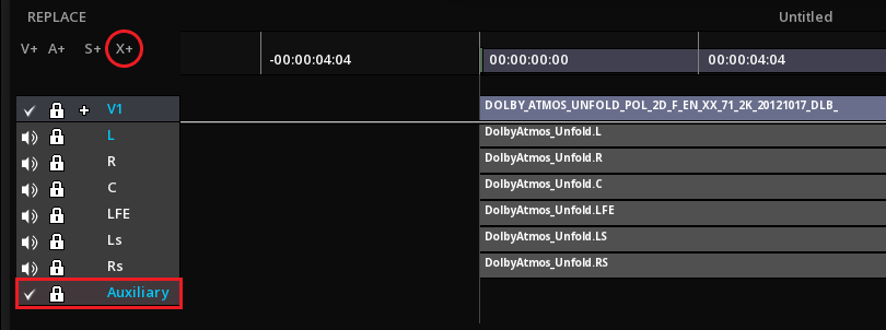
-
Place your Dolby audio metadata track in synch with the first frame of your content.
In case of several reels, you can have different MXF files for each of them.
All reels that contain a Dolby Atmos track shall also contain a Main Audio Track. If there are reels with no Dolby Atmos audio track, the Main Audio track must have the same number of channels as the Main Audio tracks in the reels that do have a Dolby Atmos track.
You can cut auxiliary tracks like you do for video and audio. However if you need to, this MUST happen at the reel boundaries. If the auxiliary MXF track is longer than the reel, you can set entry points just like for video & audio.
|
MIST is able to generate silence on the tracks but it can not create immersive audio metadata on part of the composition that does not contain one. This needs to be done in the audio mastering software that generated the metadata tracks. That’s why you cannot have any editing "gaps" on the ATMOS or DTS-X track. It must cover the entire span of the reel. |
|
For now, it is not possible to perform a downmix with Dolby Atmos. |
20.11.2. Export the Dolby Atmos DCP
-
As soon as your timeline is ready to be exported as a DCP, go to the Master Delivery.
|
The use of Dolby Atmos technology involves the use of the SMPTE format for creating the DCP. |
-
From the AUDIO page select Wild Track Format as 14 or 16 channels. The Wild Track audio layout is used according to standard, not the SMPTE MCA.
Whether you choose WTF 14 or 16, the synchronization signal will be generated on channel 14 provided for this purpose according to the ISDCF recommendations. If information is already on channel 14, it will be overwritten when the DCP is rendered. Main audio tracks will be rendered because a synchronisation signal is generate on channel 14 and therefore you canot reuse previously encoded audio MXFs.
|
Do not confuse the channel 14 sync track generated at rendering with the MXF metadata auxiliary track that you placed in your timeline. |
|
Auxiliary Data track file encryption: KDMs created for a composition with Dolby Atmos shall have the audio watermarking turned off on channel 14 in order to preserve the sync track. Do not forget to desactivate the Audio Forensic marking in the SECURITY page. |
20.12. Creating a DCP with DTS-X
MIST allows the wrapping of DTS-X audio tracks in a DCP. The process is the exact same one described for creating a Dolby Atmos DCP
21. IMF MASTERING
This Chapter describes how to create and import IMF packages. This feature is available with MIST Studio only.
21.1. Export an IMF
Once the DSM has been properly assembled in the timeline, you can use the Master Delivery panel to create your IMF packages.
21.1.1. Accessing the Master Delivery panel
The Master Delivery panel is accessible through the DELIVER button located at the bottom of the timeline representing your composition.
When Interoperable Master Format is selected, you can see the specific settings required for the IMF creation:
| Composition Playlist |
The composition playlist page is another important step where you define the title and kind of content. |
| Content Versions |
This is where you will manage the content version list of the IMF. |
| Locales |
This page allows you to manage settings referring to the local list. |
| Output Profile List |
Allow to determine the output profiles list that will be exported. |
| Sidecar |
Allow to associate any sidecar file to the IMF. |
| Packing List |
Allow to add some annotations and information about the issuer for the packing list. |
| Asset Map |
Allow to add some annotations and information about the issuer for the assetmap. |
| Security |
Choose to add a signature or not. |
| Naming |
Allow to customize the file names and have a preview of it. |
21.1.2. General settings
In this page you will be able to define the general information about your IMF package.
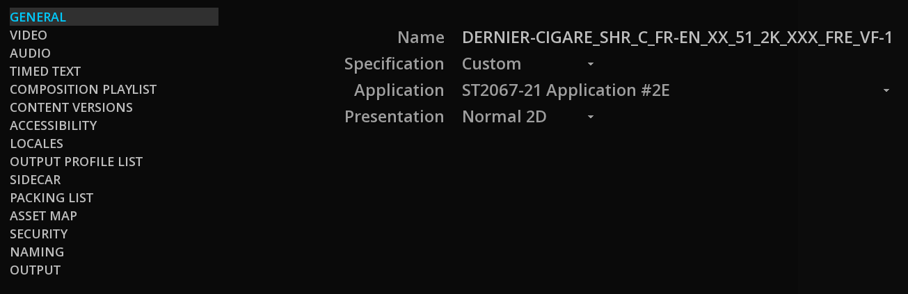
Name
The first parameter that you need to define is the name of your IMF package. By default this name will be initialized with the project name.
Specification
In order to save time and avoid errors, templates meeting the current specifications of studios, OTT and broadcasters are available as a drop-down menu. These pre-existing settings automatically apply the right settings in the Video and Audio pages :
|
Only specifications that are compatible with your composition settings are shown. |
-
Select Custom for choosing manually the IMF Application.
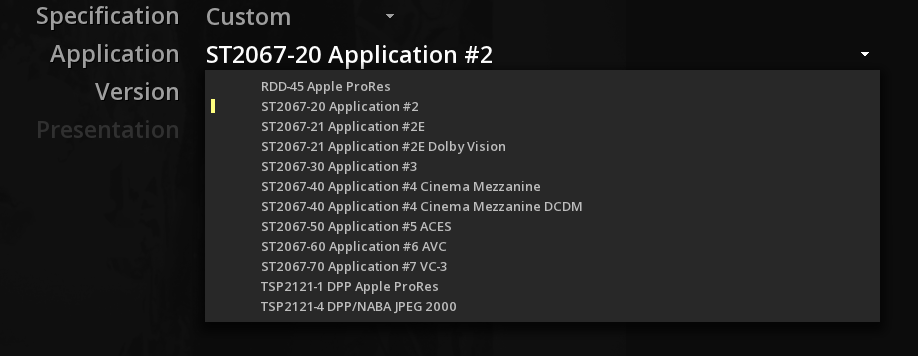
21.1.3. Video
The Video allows to configure all the settings related to the video essence for a specific IMF Application.
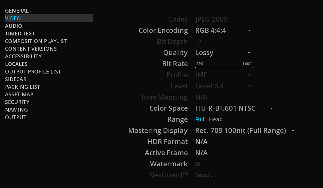
Depending on the Application chosen, the Color Encoding and Quality parameters can be chosen for the codec.
| Quality |
You can encode JPEG2000 either Lossy or Lossless |
| Color Space |
The Color Space parameter will provide you with a choice of standard color space specifications that the selected Application Type supports. Please note that no color conversion is done at this stage. The Color Space parameter simply specifies the color space of the material on the timeline. |
| Range |
The Range parameter will define if the material is using the full code range or the head code range. |
21.1.4. Composition playlist properties
Besides the general settings as well as the video and audio parameters, it is important to define the composition’s playlist metadata. While most of the parameters here do not have an influence on the readability of the package, it is nevertheless worth making sure that the information here is compliant with the requirements of the entity that you deliver the master to.
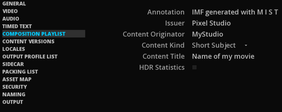

21.1.5. Content Versions
In this page, you can identify the content represented by the Composition Playlist.
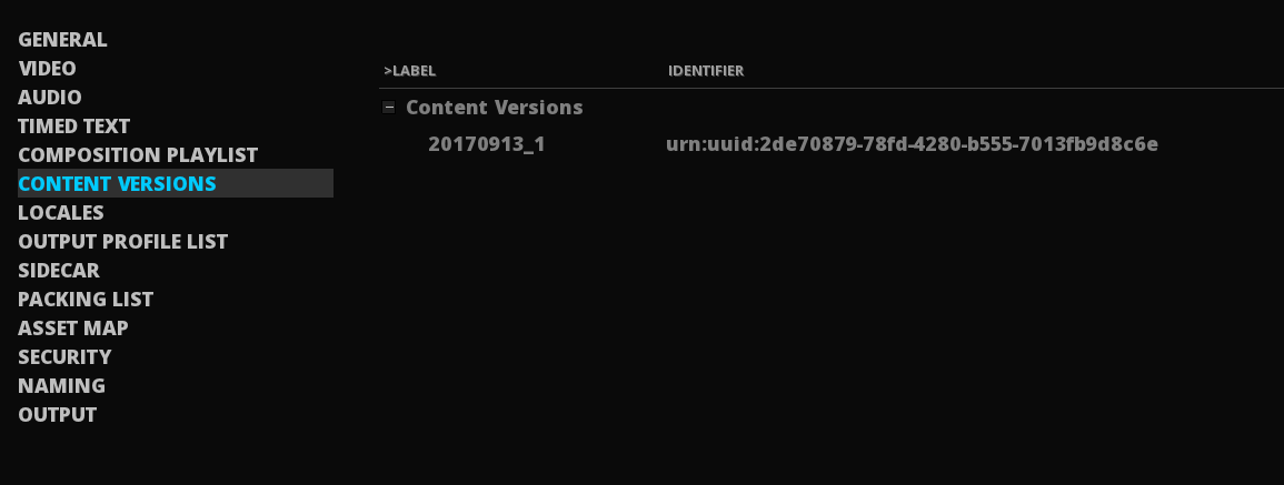
Edit the Label and the Identifier by double-click on their related field then write informations. Press ENTER to confirm your modification.
You can add a content version, delete one or reset the list by selecting the content version from the existing list then clicking on the dedicated action button:
21.1.6. Accessibility
Some delivery specifications require accessibility information. Use this page to add the metadata for signing and open captions.
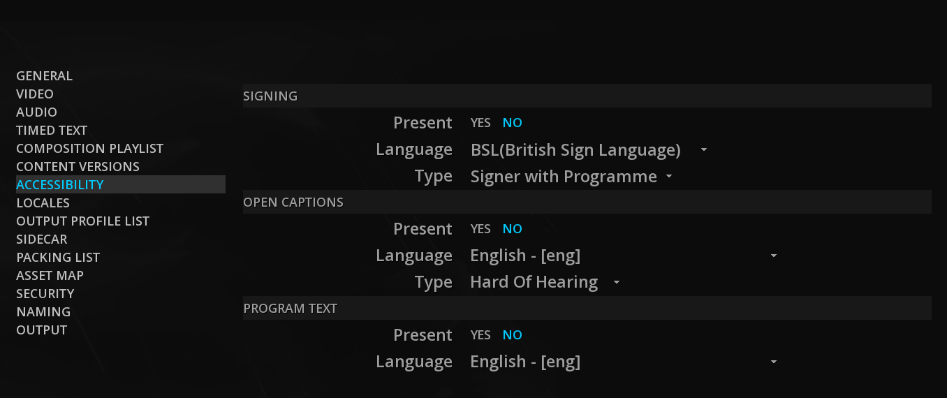
21.1.7. Locales
In this page, you can define each locale element contained in the locale list in order to specify the intended audience of the composition especially region, language and maturity rating.
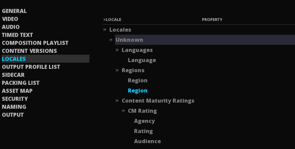
-
To create a locale, click on the
+button. -
For each sub-section, select the setting to detail (e.g Languages)
-
Click on the
+on the right side of the panel. This button is visible when moving the cursor on it.
21.1.8. Output Profile List
The Output Profile List (OPL) contains the technical transcoding instructions for a specific output format. Even if they are empty, they may be required for specific deliveries.
|
OPL can only refers to one CPL. |
You can create a human-readable annotation if desired as well as changing the Issuer.
The OPL Generation settings allow to embed or not an OPL:
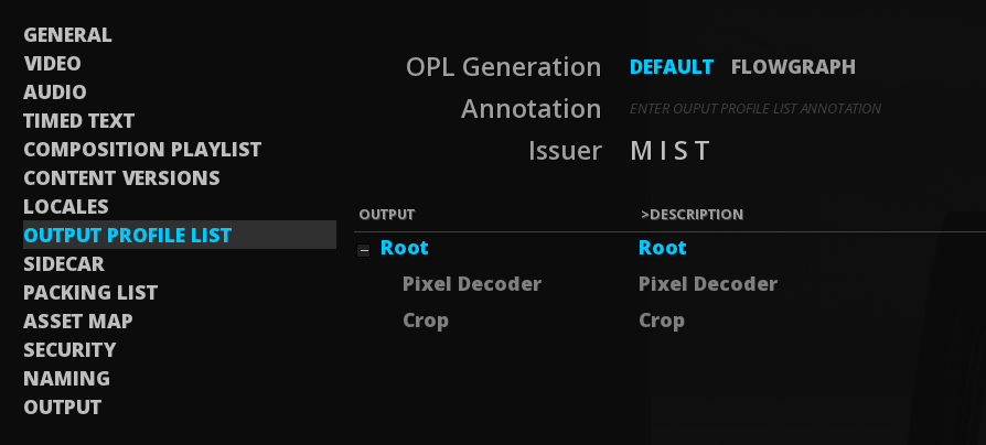
| DEFAULT |
if selected, no OPL will be embedded. |
| FLOWGRAPH |
by clicking on this setting, the OPLs created in the flowgraph of the Render module will be exported. |
The OPLs created in the flowgraph of the Render Module are not editable in this panel. This is an informational list.
21.1.9. Sidecar
It is possible to associate any type of file to an IMF package, for example a an XML file or a PDF report :
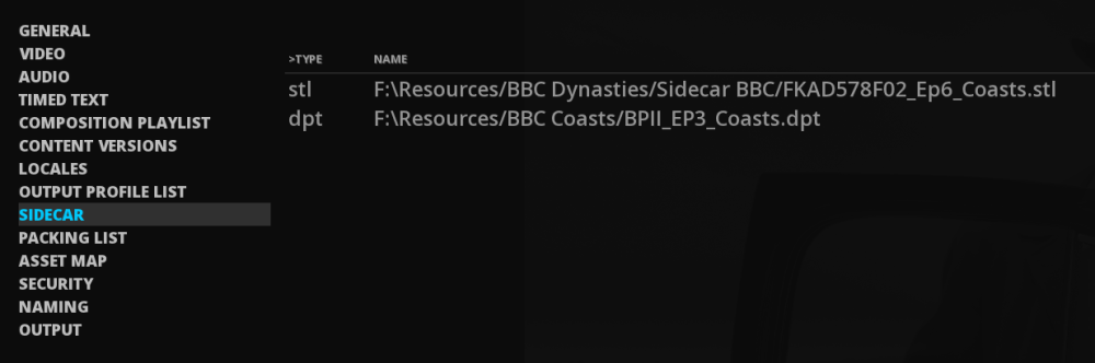
-
To add or delete a sidecar file to the package, click the + or the - button at the bottom left of the list. You can also refresh the file list:

-
Select the file and click on OK in order to add it on the list.
21.1.10. Packing List
There are two settings in the packing list page with user text fields, allowing you to enter custom information:
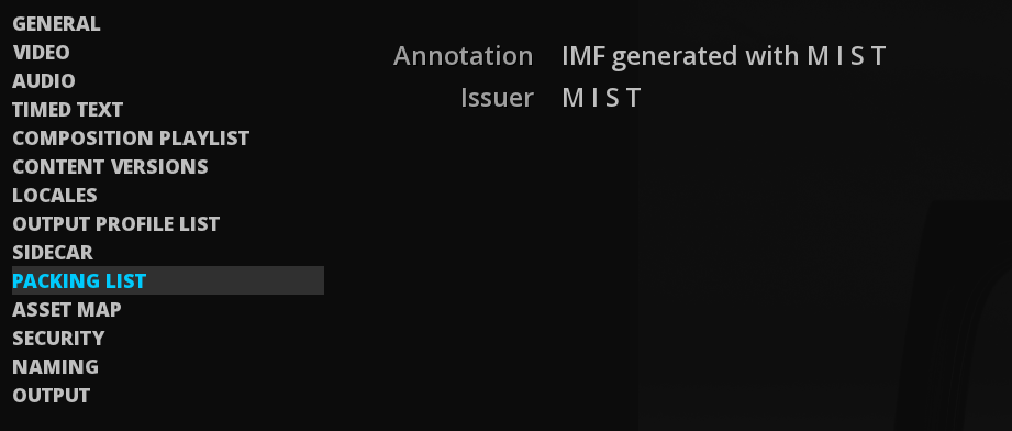
| Annotation |
The Annotation text field allows you to add a custom name as a metadata embedded within the actual Packing List. |
| Issuer |
The Issuer text field is a simple metadata which is embedded in the Packing List permitting to identify the technician or tool that created the IMF. |
21.1.11. Asset Map
Like the packing list page, you can add some annotation as well as some precision regarding the Issuer into the appropriate field:
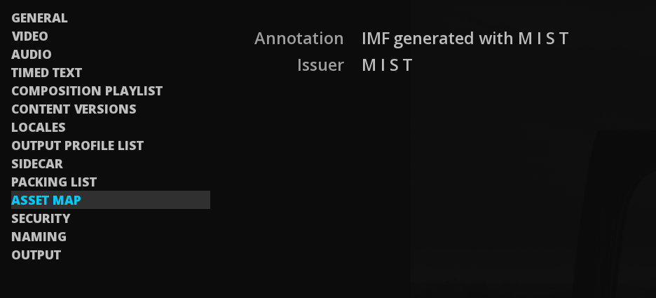
21.1.12. Security
To date, there is no encryption of the content of an IMF.
Nevertheless, it is possible to apply a signature to the CPL by clicking the YES or NO button:
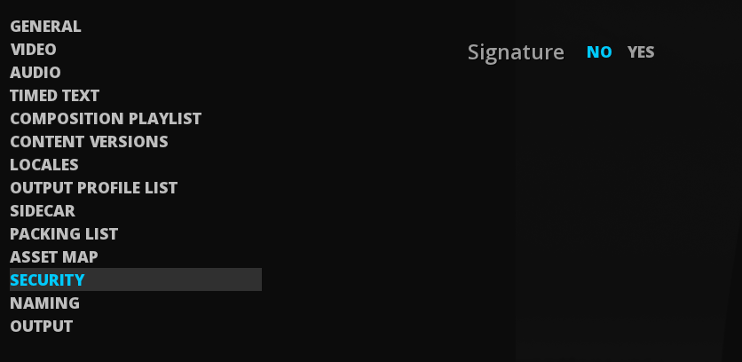
The signature uses a X.509 certificate that contains the entire certificate chain.
21.1.13. Output settings
In this OUTPUT page you can select the directory where the IMF will be generated.
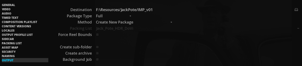
-
Click the BROWSE icon on the right to select the Directory.
Package Type
Before launching the export, you must select the type of package you want to create.
| Full |
The Full package creates a complete IMP at the desired location. |
| Differential |
In MIST, a supplemental package is called a «Differential Package». It means that a new package will solely include the new assets. This package will need the original version to be playable. |
| Encode & Relink |
This package type uses the hardlink technology. It does the same packaging type than the Full Package but it’s an instant process. You need to export this package in the same location than the original package. It is useful when you need to consolidate one IMF CPL from a multiple version. |
|
Differential and Encode & Relink are only possible when the composition is in Versioning mode. |
Method
For Differential and Encode & Relink packages types you can select different Methods for packaging:
| Create New Package |
Will create a common supplemental package inside the original one. |
| Update Package & New Packing List |
Will create a new PKL for each CPL. |
| Update Package & Update Packing List |
Will keep only one PKL that refers all the IMF essences. |
|
If you create several packing lists make sure that they have a different name in the annotation field, see chapter Packing List. |
When choosing the update packing list option, a new drop-down menu is available below, in order to choose the PKL which has to be updated:
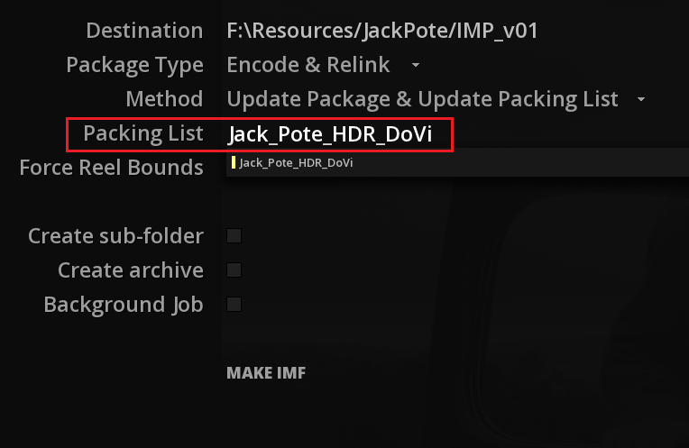
Force Reel Bounds
Click Force Reel Bounds allows to create a single video segment without keeping the clips cuts:

|
This operation is strongly recommended when exporting a Dolby Vision IMF. If not, you will have all the Dolby Vision metadata cut encoded as being independent video asset. |
Create sub-folder
You can decide to create a sub-folder or not when creating an IMF by clicking the checkbox.
21.2. Importing an IMF package
Once the IMF is imported within a composition, all the elements in the timeline are ready for screening, quality control, etc.
21.2.1. Drag & Drop an IMF
Refer to chapter Media Import Drag & Drop
|
If the IMF has differential or supplement packages then their additional essences (if any) are imported to the same chosen media folder as the original IMF’s essences. Each CPL of the package will be a Composition of the Project. This way the operator may import a multiple CPLs IMF in a single process and easily switch between the different Compositions. |
22. MASTER VALIDATION
It is possible to validate a master according to a Compliance Test Plan.
The compliance test plan verifies that the content is valid in terms of standards and or delivery specification.
For now, the following masters can be validated:
-
DCP packages
-
IMF packages
-
XAVC/RDD32 masters
-
ARD/ZDF High Definition Format
-
AS-02 masters
-
AS-07/RDD48 masters
-
AS-10 masters
-
As-11 masters
-
Degeto DI masters
-
Dolby Mezzanine masters
-
MXF Op-1a masters
-
XDCAM/RDD9 masters
The validation of IMF packages with Photon is also possible.
22.1. Validate a CPL
You can perform a validation for a particular CPL in the case of an IMF or a DCP package.
→ In Command Panel / Compositions, select and right-click the composition and choose Validate to open the Validation panel:
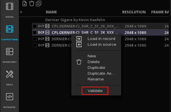
|
To validate a package with multiple compositions, select first all the CPLs from the Composition list then right-click and Validate. They all will be included in a single validation report. |
The validation of a master consists in the application of several test plans. By default all the tests are selected, and marked as QUEUED, but you can exclude individual tests or test plans by a click in the related check box(es). If a test is excluded, its status becomes N/A.
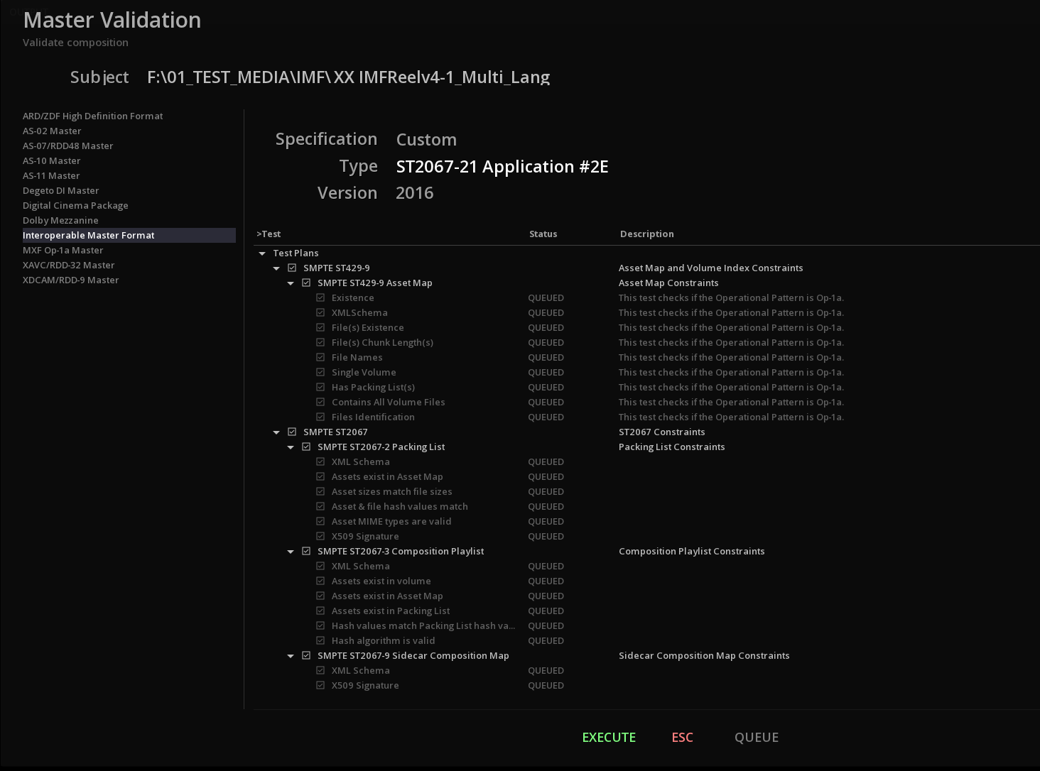
You need to define the desired Specification, Type (or application) and Version to test using the related drop-down menus.

→ Select EXECUTE to launch the validation
→ Select QUEUE* to process the validation in background or using TORNADO
|
*QUEUE is only available when the background rendering is possible or when a TORNADO is connected. |
22.2. Validate a Media
Is is also possible to validate a specific media.
→ In the MEDIA bin, select and right-click the composition and choose Validate to open the Validation panel.
Proceed as stated above to define the type of validation.
22.3. Validation Report
22.3.1. Validation result
Once the validation has been performed, an indication of the status for each test is displayed:
| PASSED |
the test was passed successfully. |
| WARNING |
the test has failed, but this should not prevent to play or ingest the media / composition. |
| FAILED |
the test has failed |
22.3.2. Export of Validation Report
You can export the validation as a PDF or a XML Report.
→ Once the validation has been completed, click on EXPORT on the bottom left of the panel.
→ Browse the files to the desired location for saving the report
→ Choose a name for the file
→ Use the File Type drop-down menu to select the type of report:

→ Validate with OK
22.4. Understanding MT Validation Tests
In this section you will find some detailed explanations of different validation tests performed for DCP and IMF Packages.
22.4.1. DCP Validation
Conformity
This test checks that the all assets including the ASSETMAP follow the VOLINDEX compliance (i.e. strictly either SMPTE or InterOp).
| A failure on this tests may prevent ingest or playback. --- |
Composition Playlist
- Is TKR (Theatre Key Retrieval) Enabled
-
This test checks that Theatre Key Retrieval (TKR) is enabled for the Composition Playlist(s).
| A failure on this test DOES NOT prevent ingest or playback. |
- Reel & Track Intrinsic Durations Match
-
This test checks that the reel intrinsic durations and track file intrinsic durations match.
| A failure on this test could prevent ingest or playback. |
- Reel Durations Are Valid
-
This test checks that the reel durations match the asset durations. A failure on this test could prevent ingest or playback.
- Reel Tracks Are Homogeneous
-
This test checks that all the reels of a Composition Playlist have the same track configuration (i.e. picture/audio/subtitles).
| A failure on this test could prevent ingest or playback on some systems. |
- Reels Have Audio
-
This test checks that the reels have an audio track.
| A failure on this test could prevent ingest or playback. |
- Reels Have Picture
-
This test checks that the reels have a picture track.
| A failure on this test could prevent ingest or playback. |
- Track Encryption is Homogeneous
-
This test checks that the tracks across the reels have a homogeneous encryption status.
| A failure on this test should not prevent ingest or playback. |
Key Delivery Message
- Lifetime Is Valid
-
This test checks if the lifetime of the Key Delivery Message(s) matches the lifetime of the signing certificates.
| A failure on this test will prevent the ingest of the KDM(s). |
- Metadata Is Valid
-
This test checks if the metadata in the Key Delivery Message(s) is valid.
| A failure on this test will prevent the ingest of the KDM(s). |
- X509 Signature
-
This test checks for the presence of the X509 digital signature in the Key Delivery Message(s).
| Digital signature is mandatory, if not present the KDM(s) is/are not valid and ingest will fail. |
Trackfile(s)
- Frame Boundaries Are Valid
-
This test checks that the first and last frame of the track file can be accessed. A failure on this test could prevent ingest or playback. This test checks that the first and last samples of the track file can be accessed.
| A failure on this test could prevent ingest or playback. |
- Trackfile(s) last at least one second
-
This test checks that the trackfiles last at least one second.
| A failure on this test could prevent correct playback on some old servers. |
- Picture Characteristics Are Valid
-
This test checks that the characteristics of the picture trackfiles are valid.
| A failure on this test could prevent ingest or playback. |
- Picture Data Rate Is Valid
-
This test checks that the bitrate of the picture trackfiles is valid.
| A failure on this test could prevent correct playback. |
- Sound Characteristics Are Valid
-
This test checks that the characteristics of the sound trackfiles are valid.
A failure on this test could prevent ingest or playback.
- Subtitle Font File Resources Are Valid
-
This test checks that the font file resources are valid (i.e. must be OTF or TTF format).
| A failure on this test could prevent ingest or playback. |
- Subtitle Font File Sizes Are Valid
-
This test checks that the font file sizes are valid (i.e. do not exceed 640kB for InterOp).
| A failure on this test could prevent ingest or playback. |
22.4.2. IMF Validation
Composition Playlist
- Has Extension Properties
-
This test checks the presence of the application ExtensionProperties in the Composition Playlist(s).
- Has Timecode
-
This test checks the presence of the timecode information inside the Composition Playlist(s).
- Edit Rate Is Homogeneous
-
This test checks if the EditRate of the resource(s) matches the Edit Rate of the Composition Playlist(s).
- Has At Least One Content Version ID
-
This test checks if at least one ContentVersion instance is present in the Composition Playlist(s).
- Has At Least One Main Audio Virtual Track
-
This test checks if at least one MainAudio virtual track is present in the Composition Playlist(s).
- Has Exactly One Main Image Virtual Track
-
This test checks if one and only one Main Image virtual track is present in the Composition Playlist(s).
- Has Homogenenous Virtual Track Durations
-
This test checks that all the virtual tracks in the Composition Playlist(s) has the exact same duration.
- Segment Durations Are Valid
-
This test checks that the duration of segments is valid. The duration constraints depended on the edit rate. For non-integer edit rates the duration of a segment must be a multiple of 5 frames.
Output Profile List
- Composition Playlist Exists In Volume
-
This test checks that the Composition Playlist referenced by the Output Profile List exists in the volume. A warning indicates that the Composition Playlist is external to this volume.
- Has Exactly Once Preset Macro
-
This test checks that Simple OPLs contain a single Preset Macro instance.
| OPLs with more than one Preset Macro are invalid and result in an ingest failure. |
- Macro Names Are Unique
-
This test checks that each macro in the Output Profile List(s) has a unique name.
| Duplicate names will result in an ingest failure. |
- Preset Macro Is Defined
-
This test checks that Preset Macro(s) use a predefined URI known to the local host.
| Unknown URIs will not trigger any preset macro processing. |
- X509 Signature
-
This test checks for the presence of the X509 digital signature in the Output Profile Lists(s).
| Digital signature is optional, unless the assets are encrypted. |
- XML Schema
-
This test checks the XML schema of the Output Profile List file(s).
| An error in the XML schema validation may result in an ingest failure. |
Trackfile(s)
- Essence Boundaries Are Valid
-
This test checks that the first and last frame/sample of the of a track file can be accessed.
| A failure on this test could prevent ingest or playback. |
- Image Characteristics
-
This test checks the image characteristics of the track files against the the Application Specification constraints.
| A failure on this test may prevent ingest and/or playback on some systems. |
Asset Map
- Contains All Volume Files
-
This test checks if all the files contained in the volume are referenced in the ASSETMAP file.
| A volume that contains non referenced files might fail to ingest. |
- Exists
-
This test checks the presence of the ASSETMAP file at the root directory of the volume.
| A package cannot be opened without this file. |
- File Names
-
This test checks that all the files listed in the ASSETMAP have a name that is compliant with the restrictions listed in ST429-9:2014 Annex A. These restrictions imply that path segments and file name do not contain other characters than: {a..z, A..Z, ., _, -}.
| File names that does not follow the rules listed in ST429-9:2014 Annex A may fail to ingest and/or prevent playback. |
- File Sizes
-
This test checks that all the files listed in the ASSETMAP have a size that exactly matches the stored size.
| A file with a size different from the one found in the ASSETMAP is probably corrupted and may fail to ingest. |
22.5. Photon
Photon is an open source tool for parsing, interpreting and validating an Interoperable Master Package. This validation test is a supplemental tool to check the IMP.
Photon v 4.8 is currently supported.
|
Running Photon requires Java JRE v 1.8 or higher. Please refer to https://github.com/Netflix/photon for more information. |
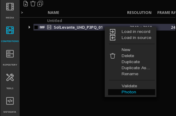
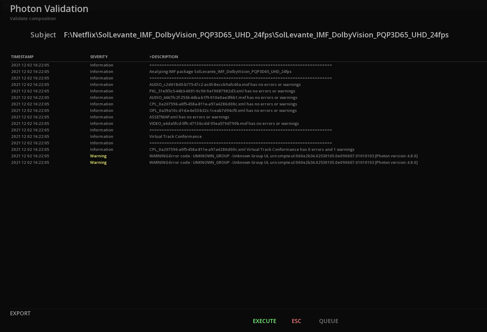
23. WORKING WITH TAPES
23.1. Tape Capture
In order to digitize still image sequences and embedded digital audio signals using the SDI input of the video board installed in your MIST system you can use the Capture module.
→ To access the Capture module, click on the CAPTURE button on the bottom menu of the timeline.
If a valid SDI video signal is connected to the input of your video board you will see the video signal in the Capture Viewport display window in the upper side of the module. This viewport allows you to visualize the current location of the external video player’s position, whether it is a VTR, a VDR or a telecine machine and to monitor the playback as the capture process is performed.
There is two pages available for setting the parameters of the capture: * Configuration, for the general settings * Capture, for choosing the format for capture.
23.1.1. Configuration
This page allows you to configure the general settings based on the video IO card capability.
Control Settings
| Comm Port |
For connecting a device using the SONY 9pin protocol |
| Device Type |
Display the device connected using the SONY 9pin protocol above. |
| Preroll |
Select the number of seconds for preroll |
| Timecode Source |
Select from which source you want to get the timecode from (SDI = RP188 or serial = RS422) |
Video Settings
| Source |
depending on the received signal, select if you want a SINGLE or DUAL input. |
| Signal |
Displays the resolution and frame rate of the signal received |
| Scalling |
Choose if you want to capture the full signal or the legal range (head) |
| Format |
Select the type of format you want to receive the signal from (depends on the video IO card capabilities) |
| Ref Source |
Display reference source information FREERUN or EXTERNAL if a Gen lock is present. |
23.1.2. Locating to a specific time code
The time code value displayed directly below the viewport shows the current time code position of the external video device controlled by the VTR comm port (Sony 9-pin) of MIST. You may use this same time code display to enter a locate cue point.
-
left mouseclick on the time code position value. (It will turn blue as shown above). -
Enter a new time code value with the number pad of your keyboard and press Enter. The external video device will locate to that point and come to a full stop.
23.1.3. Define Capture parameters
The Capture parameters allow you to choose the desired time code source, name the clips to be captured, chose their destination folder on your media storage volume, chose the format for the video and the audio.
Clip settings
| Name |
You must type a unique clip name in the Clip Name field. If you capture another file using the same name, then MIST will add _2 at the end of the second file captured. |
| Reel |
You may optionally define a reel name as well to further distinguish your captures. |
| Destination |
You must choose a destination folder for your capture. Use the browse icon to navigate to the desired sub folder within your media storage volume. All captured files will be available upon exit of the Capture Module in the project media bin at the current directory. |
| Pixel Format |
Select the desired pixel format (8, 10 bit,etc) |
| Format |
Use the Format drop-down menu to chose the video file format that you will use to perform the capture. |
Video Settings
All the parameters are dependent of the type of output format chosen and may not be available for all the formats.
| Compression |
For image sequences. Depending on the format chosen the compression types will vary or not be available at all. |
| Quality |
Select the desired compression quality |
| Profile |
Select the desired profile for the format |
| Level |
Select the desired level for the format profile |
| Byte Order |
The Byte order allows you to choose from Little or Big Endian if the format allows for you to choose. |
23.1.4. Capturing
Crash REC
The Crash Rec function allows to record the signal played back from the external video player without any Sony 9-pin control.
-
Put the external video player in playback mode and click on red Rec button at the desired moment to begin recording image sequences to your media storage volume.
-
To end the capture process click on STOP.
The captured files are automatically referenced in the current repository of the project' Media Bin.
|
During capture, the image preview in the viewport is not frame accurate because all the resources of the system are focused on writing the image on the discs. |
23.2. Tape Record
In order to lay-back video and audio tracks from the time line of MIST to an external SDI Video recording device using the SDI output of the video board installed in your MIST system you must use the Record module. The Record module allows you take control of the external video recorder device that is connected through the VTR serial comm port, defined in the Settings menu of the composition.
The Record module is part of the composition and is accessible from the Action Menu (right-click on the Viewport and choose Record). Clicking on Record calls up the Record module as shown below. If your external video recorder device is properly configured to be remote controlled through its Sony 9-pin serial input port, you will be able to cue it up to the desired location to define the in point by using the transport functions under the viewport display. The Viewport display in the top left-hand corner itself shows the video content in MIST’s timeline. In order to view the content on the external video player you will need to display it on an external video monitor.
The audio PPM display in the top right-hand corner shows the audio tracks in MIST’s timeline. You may play out up to 16 audio tracks through the embedded SDI signal from MIST to your external video player. The actual number of audio tracks that your external player will be able to capture will depend entirely upon the capabilities of the video player itself as well as the destination format used to record audio and video.
23.2.1. Set the In and Out points in the Timeline
The first step to prepare for a Record lay-back to an external video recorder using the Record Module is to define the section of the MIST timeline you wish to record by setting an In point and an Out point.
-
Cue the play cursor of MIST and press I to set the In point (or click on the In point time code value box and type a time code value and press Enter)
-
Cue the play cursor of MIST to the desired out point and press O (or enter an out point in the Out point value box and press Enter)
These In and Out points are essential to the following Record process and must be preformed before entering the Record Module (Right click on the MIST viewport and chose Record from the Action Menu).
23.2.2. Cue up your video recorder device
The time code value displayed in RECORD CUR shows the current time code position of the external video device controlled by the VTR comm port (Sony 9-pin) of MIST. You may use the transport buttons located directly below the viewport display to cue the external video recorder device. You may shuttle play, playback, fast rewind, fast forward, step forward or back frame by frame, stop the transport or eject the cassette of the VTR (if present).
Use the transport functions to cue up your external video recorder device to the exact desired punch-in point where MIST will automatically begin the lay-back process to the external video recorder device.
Enter the Punch In Point of the external video recorder
Once you have determined the exact in-point that you wish to punch record in at on your external video recorder device you must enter that time code value in the In Point value box located directly beneath the transport buttons in the Record Module.
-
right-click on the In Point time code value (it will turn blue)
-
Type in the desired punch in point for the external video recorder device and press Enter to validate.
23.2.3. Choose the record type
Assemble mode
Assemble mode is used to perform a recording to your external video recorder device by activating all input channels for recording simultaneously. This will overwrite any previous recordings on all tracks of a video cassette (including video, soundtracks and time code tracks) during the lay-back recording process. Use this mode with care when using cassette based VTR machines, as you will not be able to recover any mistakenly overwritten tracks.
Insert mode
Insert mode is used to perform a recording to your external video recorder device by selectively activating only those tracks you wish to record to during the lay-back process. Use this mode to record only the video or only certain audio tracks back to your external video recorder device while preserving the inactive tracks.
When you activate Insert mode by clicking on the INSERT button the individual tracks that are available for activation, as detected by the VTR comm port (Sony 9-Pin), appear in solid white or blue instead of appearing greyed-out. Click on the tracks you wish to activate (blue) or deactivate (white).
23.2.4. Set the Video and Audio delay
Video and audio Delay
As you are working from the MIST timeline to an external SDI video recording device you may discover that you need to compensate for delays created by other external devices, like video routers or audio processors, that may introduce line delays between the time code and the audio or video signals to your recording device. This results in picture and sound tracks that are no longer in-sync with the time-code once played back from the external recorder. MIST allows you to compensate for these delays introduced by external equipment with the Video and Audio Delay offsets in the Record module.
You may enter positive or negative frame values in the frames fields to delay or advance the signals individually.
-
Click on the Delay value field (it will turn blue).
-
Type in a positive value or a negative value (i.e. -3).
-
Press Enter to validate your frame delay offset.
23.2.5. Source Record & Duration time code fields
Source time code fields
Source time code fields show the In Point (IN), Current play cursor position (CUR) and the Out Point (OUT) of the MIST timeline. These fields may not be altered from within the Record Module. They are only intended to indicate the current these values. In order to modify theses fields you must exit the Record Module and set the In and Out points from the Project Module (F3).
|
It is important to understand that the In Point of the composition in the MIST timeline is aligned to the Punch In Point of the external video recorder. The record module aligns these two points to correspond at the moment of record punch-in. This is the essentially offset between the two time codes of the two machines. |
The Source OUT value shows the Out Point of the composition in the MIST timeline. The time between the Source In and the Source Out points defines the Duration value. This is the amount of video and audio that will be layed-back to your external video recorder device during the Record process.
Record time code fields
-
Record IN shows the In Point that you chose as the punch-in point on your external video recorder device.
-
Record CUR shows the current position of your external recorder.
-
Record OUT shows the punch-out point that is automatically calculated by the Record Module to correspond to the length of the entire operation of laying-back audio and video to your external video recorder.
Source & Record transport indicators
The Source & Record transport indicators display the current status of but MIST and the external recorder at all times. Theses indicators may be useful to diagnose difficulties if a Record process fails for any reason like defining and time code value that is out of range of a video cassette, etc.
23.2.6. Record Preview & Review modes
About PreRoll
|
The RECORD PREVIEW and REVIEW functions all take into account the preroll value defined in the VTR tab of the Project Settings page. It is generally good practice to allow for ample preroll values when working with Sony 9-Pin machines to perform edit processes like the Record function. Some machines (like telecines or older VTRs) require considerably more time to establish a stable lock status than modern machines or disk-based recording devices due to their mechanical components. It is generally good to start with at least 4 seconds of preroll and adjust if necessary. |
Preview through your external video recorder
Once all the parameters are properly set as described in the previous sections you may wish to rehearse the recording process through your external video recorder without actually recording anything just to make sure your offsets and punch in/out points are accurately placed. This is achieved by launching the Preview function.
-
Click on the Preview button.
MIST performs a complete simulation of the actual record process without recording any material by switching your external video recorder to its input mode on active records tracks. This mode allows for adjustments to be made to your record parameters without overwriting any precious content on tape accidentally.
Record to your external video recorder
Once all the parameters are properly set as described in the previous sections you may use the Record button to launch the record process and layback your audio and video tracks to your external video recorder.
-
Click on the Preview button.
MIST performs the actual record process cuing up both the MIST timeline and the external video recorder to the appropriate preroll value. This process will permanently replace video and audio signals on active recording tracks of a conventional VTR deck.
Review the record pass performed on your external video recorder
Once the record pass is performed on your external video recorder, you may wish to verify it by using the Review function.
-
Click on the Review button.
The Record module cues up the external video recorder to the preroll value before the In point and puts the video recorder into play until punch-out point is reached, at which time the recorder is placed in stop.
APPENDICES
1. Console
The Console tab in the Control Panel displays information about the image processing pipeline performances.
Different gauges display the buffer usages of the key devices while performing the playback of a media.
| Storage |
Usage of the media storage for the content currently on the timeline |
| GPU |
Usage of the GPU buffers |
| Video |
Usage of the buffers for transfers between GPU and Video IO card |
| Device |
Usage of the buffers transferred by the Video IO card |
| Drop |
display information in the case of drop frames |
2. Input File Formats Support
2.1. Compositions
| Format Name | File Extension(s) |
|---|---|
Advanced Authoring Format |
.aaf |
D-Cinema Composition Playlist |
.xml |
EDL CMX 3600 |
.edl |
Final Cut Pro |
.xml |
Final Cut Pro X |
.fcpxml |
IMF Composition Playlist |
.edl |
2.2. Camera Files
| Camera | Models | Format Names |
|---|---|---|
Apple |
iPhone |
h.264 QT MOV |
ARRI |
Alexa (B6W, LF, SXR, SXT, XR, XT, 65) |
ARRIRAW (incl. 4:3), ARRIRAW MXF |
BlackMagic |
Cinema, Pocket Cinema, URSA |
Blackmagic RAW |
Canon |
EOS 1D / 5D / 7D |
h.264 QT MOV |
GoPro |
Any |
h.264 MP4 |
Nikon |
DSLR cameras |
NEF DSLR RAW |
Panasonic |
Varicam 35 |
Panasonic VRW RAW |
Phantom |
4K Flex |
.cine RAW |
RED |
Dragon |
REDCODE RAW (R3D) |
SONY |
F65, F55, F5 |
SonyRAW |
2.3. Image Sequences
| Format Name | File Extension(s) | Comment |
|---|---|---|
Cineon |
.cin |
|
DPX |
.dpx |
See DPX Support |
Targa |
.tga |
|
TIFF |
.tif, .tiff |
|
ARRI |
.ari |
|
SGI |
.sgi, .rgb |
|
JPEG |
.jpg, .jpeg |
|
JPEG2000 (J2K) |
.j2k, .j2c |
|
JPEG XS |
.jxs |
|
JPEG High Throughput |
.jph |
|
BMP |
.bmp |
|
PNG |
.png |
|
Photoshop PSD |
.psd |
Import composite image only. |
OpenEXR |
.exr |
|
ERIMovie |
.eri |
|
Chyron |
.chr |
|
Media Logic Artisan |
.art |
|
Rendition |
.6rn |
|
DNG |
.dng |
|
Weisscam RAW |
.fhgW* |
|
Canon RAW |
.rmf |
|
Panasonic VRAW |
.vrw |
2.3.1. DPX support
8 bit UYVY |
10 bit YUV 4:2:2 b.e. V2 |
12 bit RGB b.e. |
8 bit YUVA 4:2:2:4 |
10 bit YUV 4:2:2 Cineon b.e. |
12 bit RGB b.e. V2 |
8 bit YUV 4:2:2 b.e. V2 |
10 bit YUV 4:4:4 b.e. V2 |
12 bit RGB l.e. V2 |
8 bit YUV 4:2:2 l.e. V2 |
10 bit RGB Cineon b.e. |
|
8 bit YUV 4:4:4 b.e. V2 |
10 bit RGBA |
16 bit RGB Cineon b.e. |
8 bit RGB b.e. V2 |
||
8 bit RGB l.e. V2 |
DPX Monochrome |
|
8 bit RGBA |
DPX Alpha |
b.e. = big endian / l.e. = little endian
2.4. Video
| Format Name | File Extension(s) |
|---|---|
Advanced Systems Format (Windows Media Video) |
.wmv |
AS-02 |
.mxf |
AS-10 |
.mxf |
AS-11 DPP |
.mxf |
AS-11 D10 |
.mxf |
ARD/ZDF/HDF |
.mxf |
AVI |
.avi |
Avid MXF |
.mxf |
DV |
.dv |
FlashVideo |
.flv |
GXF |
.mxf |
D10 |
.mxf |
RDD9 |
.mxf |
Matroska |
.mkv |
MPEG-2 |
.mpg, .mpeg |
MPEG-4 |
.mp4 |
MPEG-TS |
.mts |
MPEG-TS BDAV |
.m2ts |
MXF OP-Atom |
.mxf |
MXF OP-1a |
.mxf |
Motion JPEG2000 |
.mj2 |
PhantomCINE |
.cine |
QuickTime |
.mov |
R3D |
.r3d |
WebM |
.webm |
2.5. Audio
| Format Name | File Extension(s) |
|---|---|
Audio Interchange File Format (AIFF) |
.aif, .aiff |
Waveform Audio File Format (WAVE) |
.wav |
Free Lossless Audio Codec (FLAC) |
.flac |
Dolby Atmos |
.atmos |
Digital Theater Systems (DTS-X) |
.dts |
2.7. Subtitles & Captions
| Format Name | File Extension(s) | Comments |
|---|---|---|
Cheetah Closed Captions |
.cap |
|
CineCanvas |
.xml |
|
Digital Cinema XML |
.xml |
|
EBU STL |
.stl |
|
EEG 708 Captions |
.xml |
|
Scenarist Closed Captions |
.scc |
|
Screen Electronics PAC |
.pac |
|
Sony BDN |
.xml, .png, .tif |
|
Spruce STL |
.stl |
|
SubRip |
.srt |
|
SubViewer |
.sub |
|
TTML |
.xml, .ttml |
|
Apple iTunes Timed Text |
.itt |
|
Common File Format Timed Text |
.xml |
|
DFXP |
.xml, .dfxp |
|
EBU-TT-D |
.xml |
|
Internet Media Subtitles and Captions (IMSC) |
.xml, .ttml |
Support for v1. and v1.01. Animation not supported. |
SMPTETT |
.xml |
|
WebVTT |
.vtt |
2.8. IMF Applications
The following IMF packages can be imported:
-
Application 2, 2e (Studio Profile)
-
Application 4 (Cinema Mezzanine)
-
Application 5 (ACES)
-
IMF ProRes RDD45
-
RDD 59-1 IMF Application DPP (ProRes)
-
RDD 59-2 IMF Application DPP (JPEG2000)
Supported JPEG2000 profiles:
-
Broadcast profiles, up to BPC L7
-
IMF profiles, up to 16 bit
3. Output File Formats Support
3.1. Compositions
| Format Name | File Extension(s) |
|---|---|
D-Cinema Composition Playlist |
.xml |
EDL CMX 3600 |
.edl |
Final Cut Pro |
.xml |
Final Cut Pro X |
.fcpxml |
IMF Composition Playlist |
.edl |
Avid Log Exchange |
.ale |
Advanced Authoring Format |
.aaf |
3.2. Image Sequences
| Format Name | File Extension(s) | Comment |
|---|---|---|
Cineon |
.cin |
|
DPX |
.dpx |
|
Targa |
.tga |
|
TIFF |
.tif, .tiff |
|
ARRI |
.ari |
|
SGI |
.sgi, .rgb |
|
JPEG |
.jpg, .jpeg |
|
JPEG2000 (J2K) |
.j2k, .j2c |
|
JPEG XS |
.jxs |
|
JPEG High Throughput |
.jph |
|
BMP |
.bmp |
|
PNG |
.png |
|
Photoshop PSD |
.psd |
Composite uncompressed PSD only. |
OpenEXR |
.exr |
|
ERIMovie |
.eri |
|
Chyron |
.chr |
|
Media Logic Artisan |
.art |
|
Rendition |
.6rn |
3.3. Video
| Format Name | File Extension(s) |
|---|---|
Advanced Systems Format (Windows Media Video) |
.wmv |
AS-02 |
.mxf |
AS-10 |
.mxf |
AS-11 DPP |
.mxf |
AS-11 D10 |
.mxf |
ARD/ZDF/HDF |
.mxf |
AVI |
.avi |
Avid MXF |
.mxf |
DV |
.dv |
GXF |
.mxf |
D10 |
.mxf |
RDD9 |
.mxf |
Matroska |
.mkv |
MPEG-2 |
.mpg, .mpeg |
MPEG-4 |
.mp4 |
MPEG-TS |
.mts |
MPEG-TS BDAV |
.m2ts |
MXF OP-Atom |
.mxf |
MXF OP-1a |
.mxf |
QuickTime |
.mov |
WebM |
.webm |
3.6. Subtitles & Captions
| Format Name | File Extension(s) | Comments |
|---|---|---|
CineCanvas |
.xml |
|
Digital Cinema XML |
.xml |
|
EBU STL |
.stl |
|
Internet Media Subtitles and Captions (IMSC) |
.xml, .ttml |
Support for v1. and v1.01. Export of image profiles not supported. Animation not supported. |
3.7. IMF Applications
The following IMF packages can be exported:
-
Application 2, 2e (Studio Profile)
-
Application 4 (Cinema Mezzanine)
-
Application 5 (ACES)
-
IMF ProRes RDD45
-
RDD 59-1 IMF Application DPP (ProRes)
-
RDD 59-2 IMF Application DPP (JPEG2000)
Supported JPEG2000 profiles:
-
Broadcast profiles, up to BPC L7
-
IMF profiles, up to 16 bit
4. Delivery Specifications support
MIST integrates numerous studios and broadcasters Delivery Specifications. They are constantly updated to match their requirements.
-
Amazon Prime
-
AMPAS
-
ARD/ZDF
-
BBC
-
Canal+
-
CNN
-
Degeto
-
Disney
-
Fox
-
HBO
-
NBC Universal
-
Netflix
-
NRK
-
RAI
-
Sony Pictures
-
Warner Bros.
5. Keyboard Shortcuts
Below is a recapitulation of the available Keyboards Shortcuts for MIST.
| TOPIC | MODIFIER KEY | DESCRIPTION |
|---|---|---|
NAVIGATION |
F1 |
Go to Project |
NAVIGATION |
F2 |
Go to Library |
NAVIGATION |
F4 |
Go to Assembler |
NAVIGATION |
F6 |
Go to Composition Analysis |
NAVIGATION |
Alt+F6 |
Go to Video Pipeline Diagram |
NAVIGATION |
F7 |
Go to Storyboard |
NAVIGATION |
F8 |
Go to Grade Library |
NAVIGATION |
F9 |
Go to Grade |
NAVIGATION |
F10 |
Go to Timeline |
NAVIGATION |
F11 |
Switch Calibrate/Timeline |
NAVIGATION |
F12 |
About |
NAVIGATION |
Esc |
Escape from current operation |
NAVIGATION |
H |
Help |
NAVIGATION |
Page Up |
Show Timeline |
NAVIGATION |
Page Down |
Hide Timeline |
NAVIGATION |
Ctrl+Q |
Exit Project |
NAVIGATION |
Alt+Ctrl+Esc |
Minimize |
CLIP MANAGEMENT |
Ctrl+Shift+P |
Show Clip Properties |
COMPOSITION I/O |
Ctrl+N |
New Composition |
COMPOSITION I/O |
Ctrl+O |
Open/Load Composition |
COMPOSITION I/O |
Ctrl+S |
Save Composition |
COMPOSITION I/O |
Ctrl+Shift+S |
Save Composition As |
OTHER |
Ctrl+F12 |
Take Snapshot |
AUDIO |
Alt+Shift+A |
Show/Hide Audio Mixer |
DISPLAY |
Shift+H |
Show/Hide Histogram |
DISPLAY |
Shift+V |
Show/Hide Vectorscope |
DISPLAY |
Shift+W |
Show/Hide Waveform |
DISPLAY |
Shift+A |
Show/Hide Audio levels |
DISPLAY |
Shift+B |
Show/Hide Bitrate |
DISPLAY |
Shift+N |
Show/Hide Luminance Meter |
DISPLAY |
Shift+D |
Show/Hide DMCVT Metadata |
DISPLAY |
Shift+M |
Show/Hide Dynamic Metadata |
DISPLAY |
Shift+P |
Show/Hide PSNR Meter |
DISPLAY |
Alt+Z |
Show/Hide Zebra |
DISPLAY |
Alt+Q |
Show/Hide Dynamic Mapping |
DISPLAY |
Alt+T |
Change time display |
DISPLAY |
F |
Fit Viewport |
DISPLAY |
Shift+F |
Toggle Full Screen Viewport |
DISPLAY |
C |
Center Viewport |
DISPLAY |
Alt+C |
Toggle Camera View |
DISPLAY |
Alt+F |
Toggle Safe Frames |
DISPLAY |
Alt+A |
Toggle Axis View |
DISPLAY |
Alt+K |
Show/Hide Color Picker Info |
DISPLAY |
Alt+Shift+K |
Toggle Color Picker Display Modes |
DISPLAY |
Alt+J |
Show/Hide Information |
DISPLAY |
Alt+1 |
Toggle Red Channel |
DISPLAY |
Alt+2 |
Toggle Green Channel |
DISPLAY |
Alt+3 |
Toggle Blue Channel |
DISPLAY |
Alt+4 |
Toggle Alpha Channel |
DISPLAY |
Alt+5 |
Toggle Mask |
DISPLAY |
Alt+B |
Toggle Active Area |
DISPLAY |
Alt+S |
Toggle Mono/Stereo |
DISPLAY |
Alt+D |
Toggle Left/Right Display |
DISPLAY |
Alt+G |
Toggle Geometry Display |
DISPLAY |
X |
Toggle Dual Viewport |
DISPLAY |
Alt+X |
Toggle Single/Dual Viewport |
DISPLAY |
G |
Lock Dual Viewport |
LUT |
9 |
Toggle LUT Computer Display |
LUT |
0 |
Toggle LUT Mastering Display |
TIMELINE |
Ctrl+Shift+F |
Fit Timeline |
TIMELINE |
Alt+Ctrl+F |
Fit duration |
TIMELINE |
Alt+Ctrl+Shift+F |
Fit All durations |
TIMELINE |
Ctrl+Shift+C |
Center Timeline |
TIMELINE |
Ctrl++ |
Zoom In Timeline |
TIMELINE |
Ctrl+- |
Zoom Out Timeline |
TIMELINE |
Alt+H |
Toggle Clip Handles |
EDIT |
Ctrl+Z |
Undo |
EDIT |
Ctrl+Y |
Redo |
EDIT |
Ctrl+A |
Select all Clips |
EDIT |
Ctrl+D |
Deselect All Clips |
EDIT |
Delete |
Delete Selected Clips |
EDIT |
Backspace |
Ripple Delete Selected Clips |
EDIT |
I |
Mark In |
EDIT |
O |
Mark Out |
EDIT |
Alt+I |
Clear Mark In |
EDIT |
Alt+O |
Clear Mark Out |
EDIT |
Ctrl+Shift+I |
Set Composition In |
EDIT |
Ctrl+Shift+O |
Set Composition Out |
EDIT |
Alt+M |
Clear Mark points |
EDIT |
Ctrl+K |
Razor at time marker |
EDIT |
Ctrl+L |
Lift marked region |
EDIT |
Ctrl+E |
Extract marked region |
EDIT |
Ctrl+J |
Join |
EDIT |
Insert |
Toggle Insert/Replace Mode |
EDIT |
Ctrl+C |
Copy |
EDIT |
Ctrl+V |
Paste |
EDIT |
S |
Select Current Clip |
EDIT |
Ctrl+Up |
Activate Layer Above |
EDIT |
Ctrl+Down |
Activate Layer Below |
EDIT |
Ctrl+Shift+L |
Lock/Unlock Active Layer |
EDIT |
Ctrl+Shift+E |
Enable/Disable Active layer |
EDIT |
T |
Insert Dissolve |
EDIT |
Y |
Insert from Source |
EDIT |
Ctrl+Shift+A |
Insert Audio layer |
EDIT |
Ctrl+Shift+V |
Insert Video Layer |
EDIT |
Ctrl+Shift+W |
Merge Stereo Video Layers |
EDIT |
Alt+Ctrl+V |
Paste Layered |
EDIT |
W |
Toggle Snap |
EDIT |
Alt+Left |
Trim In -1 frame |
EDIT |
Alt+Right |
Trim In +1 frame |
EDIT |
Alt+Shift+Left |
Trim Out -1 frame |
EDIT |
Alt+Shift+Right |
Trim Out +1 frame |
EDIT |
Alt+Ctrl+Left |
Slip -1 frame |
EDIT |
Alt+Ctrl+Right |
Slip +1 frame |
EDIT |
Alt+Up |
Slide -1 frame |
EDIT |
Alt+Down |
Slide +1 frame |
TRANSPORT |
J |
J Pressed |
TRANSPORT |
J |
J Released |
TRANSPORT |
K |
K Pressed |
TRANSPORT |
K |
K Released |
TRANSPORT |
L |
L Pressed |
TRANSPORT |
L |
L Released |
TRANSPORT |
Space |
Play Forwards |
TRANSPORT |
Ctrl+Space |
Play Backwards |
TRANSPORT |
Alt+Space |
Play Forwards Marked Range |
TRANSPORT |
Alt+Ctrl+Space |
Play Backwards Marked Range |
TRANSPORT |
Shift+I |
Go to IN point |
TRANSPORT |
Shift+O |
Go to OUT Point |
TRANSPORT |
Left |
Previous Frame |
TRANSPORT |
Right |
Next Frame |
TRANSPORT |
Shift+Left |
Previous 10 Frames |
TRANSPORT |
Shift+Right |
Next 10 frames |
TRANSPORT |
Ctrl+Left |
Previous 100 Frames |
TRANSPORT |
Ctrl+Right |
Next 100 Frames |
TRANSPORT |
Ctrl+Shift+Left |
Go to Previous Cut |
TRANSPORT |
Ctrl+Shift+Right |
Go to Next Cut |
TRANSPORT |
Home |
Go to First Frame of the Composition |
TRANSPORT |
End |
Go to Last Frame of the Composition |
TRANSPORT |
Ctrl+P |
Toggle Playback Mode |
TRANSPORT |
Shift+Home |
Go to Layer Start |
TRANSPORT |
Shift+Eend |
Go to Layer End |
TRANSPORT |
Ctrl+Home |
Go to Clip Start |
TRANSPORT |
Ctrl+End |
Go to Clip End |
TRANSPORT |
Alt+Page Up |
Previous Audio Cut |
TRANSPORT |
Alt+Page Down |
Next Audio Cut |
TRANSPORT |
Shift+Page Up |
Previous Subtitle |
TRANSPORT |
Shift+Page Down |
Next Subtitle |
LOCATOR |
P |
Go to Next Composition Locator |
LOCATOR |
Alt+P |
Go to Last Composition Locator |
MARKERS |
Alt+U |
Previous Composition Marker |
MARKERS |
Shift+U |
Next Composition Marker |
MARKERS |
Alt+CTRL+M |
Previous Segment Marker |
MARKERS |
Ctrl+Shift+M |
Next Segment Marker |
MARKERS |
Ctrl+M |
Add Composition Marker |
MARKERS |
Alt+Shift+M |
Add Segment Marker |
REELS |
Alt+Ctrl+Page Up |
Previous reel |
REELS |
Alt+Ctrl+Page Down |
Next reel |
REELS |
Ctrl+R |
Add reel |
REELS |
Alt+Shift+R |
Delete reel |
STILL STORE |
8 |
Enter/Toggle Compare Mode |
STILL STORE |
Alt+8 |
Exit Compare Mode |
STILL STORE |
Ctrl+8 |
Copy Frame to Still Store |
STILL STORE |
Ctrl+Shift+8 |
Toggle Comparator Visibility |
EVENT VIEWER |
E |
Show/Hide Event Viewer |
QUICK GRADE LIBRARY |
Q |
Show/Hide Quick Grade Library |
GRADE |
M |
Store Grade |
GRADE |
B |
Recall Grade |
GRADE |
Alt+R |
Reset correction |
GRADE |
Alt+Ctrl+R |
Reset all corrections |
GRADE |
Ctrl+Return |
Confirm Grade |
GRADE |
Alt++ |
Printer Lights RGB +1 point |
GRADE |
Alt+- |
Printer Lights RGB -1 point |
GRADE |
Alt+Numpad 7 |
Printer Lights Red +1 point |
GRADE |
Alt+Numpad 8 |
Printer Lights Green +1 point |
GRADE |
Alt+Numpad 9 |
Printer Lights Blue +1 point |
GRADE |
Alt+Numpad 4 |
Printer Lights Red -1 point |
GRADE |
Alt+Numpad 5 |
Printer Lights Green -1 point |
GRADE |
Alt+Numpad 6 |
Printer Lights Blue -1 point |
GRADE |
Shift++ |
Printer Lights RGB +1 half point |
GRADE |
Shift+- |
Printer Lights RGB -1 half point |
GRADE |
Ctrl+Numpad 7 |
Printer Lights Red +1 half point |
GRADE |
Ctrl+Numpad 8 |
Printer Lights Green +1 half point |
GRADE |
Ctrl+Numpad 9 |
Printer Lights Blue +1 half point |
GRADE |
Ctrl+Numpad 4 |
Printer Lights Red -1 half point |
GRADE |
Ctrl+Numpad 5 |
Printer Lights Green -1 half point |
GRADE |
Ctrl+Numpad 6 |
Printer Lights Blue -1 half point |
ANIMATION |
A |
Show/Hide Keyframe Viewer |
ANIMATION |
Ctrl+Shift+K |
Set Keyframe |
ANIMATION |
Ctrl+Del |
Delete Keyframe |
ANIMATION |
Ctrl+Page Up |
Previous Keyframe |
ANIMATION |
Ctrl+Page Down |
Next Keyframe |
ANIMATION |
Ctrl+T |
Keyframe transition |
ANIMATION |
Alt+Ctrl+T |
Keyframe constant |
6. MT-TN-60 Rich Text Markup Specification
6.1. Introduction
6.1.1. Overview
This document describes the Marquise Technologies Rich Text Markup used across all the products to apply advanced styling to text elements.
6.1.2. Scope
This specification is intended to give a reference to end-users on how the Rich Text Markup can be used to apply advanced styling during text rendering for subtitles and captions as well as any other place where user-defined text is rendered.
6.1.3. Syntax Structure
Rich Text Markup (RTM) uses a compact structure that supports styling commands and nested blocks called spans. Each span can have its own list of styling commands. Nested spans inherit the styling commands from the parent spans.
Text Stream
A text stream is a stream of characters that may contain Rich Text Markup as described in this document. The text stream does not contain any document layout properties such as page management or paragraph management. These concepts are out of scope and depend on the context where Rich Text Markup is used. However they may influence the default rendering of the text (e.g. default text color, default font size, etc).
Text Span
A text span is delimited by enclosing the text between curly brackets { and }. These delimiting characters have the Unicode values of U+007B and U+007D respectively. The top-level span in a nested group of spans may or may not be enclosed using the curly brackets. In that case the RTM processors assumes that the start and the end of the top-level span are defined by the start and the end of the entire block of text.
Styling Commands
Styling commands must follow the beginning of a span, by using the backslash character \ (Unicode character U+005C). Each command begins with a backslash. No whitespace character must exist between the start of a span and the list of commands and no whitespace character must exist between commands. The RTM parser will stop interpreting styling commands when encountering the first whitespace after the start of a span or a styling command.
| Command Name | Description |
|---|---|
b |
changes the current text background color, see Text Background Color |
bidi |
|
col |
changes the current text color, see Text Color |
dir |
|
font |
|
fontFamily |
|
fontSize |
changes the current font size, see Font Size |
fontStyle |
changes the current font slanting style (e.g. Normal, Italic, etc), see Font Style |
fontWeight |
changes the current font weigth (e.g. Normal, Bold, etc), see Font Weight |
opacity |
|
ruby |
|
textCombine |
|
textDecoration |
|
textEmphasis |
|
textOrientation |
|
textOutline |
|
textShadow |
Font Weight
fontWeight(weight)
The fontWeight command changes the weight of the current font within the current span.
| Parameter | Description |
|---|---|
normal |
sets the standard weight for the font |
bold |
sets the bold weight for the font |
| Property | Description |
|---|---|
Inherited |
yes |
Font Size
The fontSize command changes the size of the current font within the current span.
| Property | Description |
|---|---|
Inherited |
yes |
Font Style
fontStyle(style)
The fontStyle command changes the slanting style of the current font within the current span.
| Parameter | Description |
|---|---|
normal |
sets the normal slanting for the font |
italic |
sets the italic slanting for the font |
oblique |
sets the oblique slanting for the font (if font does not support the style, italid is used) |
| Property | Description |
|---|---|
Inherited |
yes |
7. Third-party Licenses
Marquise Technologies integrates third-party technology into its software solutions. Some of the below listed technology is available in options only.
The end-user is responsible for complying with any and all third-party terms that apply. Access to third-party software is provided for convenience only, and Marquise Technologies has no responsibility for such third-party software.
7.1. ARRIRAW SDK
The ARRIRAW SDK is provided under the 2020 ARRI Partner Program Agreement.
Copyright © ARRI AG.
7.2. Avid DNxHD & DNxHR
Avid formats are provided by the Avid Media Toolkit SDK under Avid DNxHD Unified License Agreement.
Copyright © Avid Technology, Inc.
7.3. Dolby Technologies
Dolby VisionTM is provided under the Dolby Vision Content Solutions System Agreement.
Dolby AtmosTM is provided under the Dolby Atmos Content Solutions System Agreement.
Copyright: Dolby, Dolby Vision, Dolby Atmos and the double-D symbol are registered trademarks of Dolby Laboratories Licensing Corporation.
Confidential unpublished works. Copyright 2021 Dolby Laboratories. All rights reserved.
7.4. DVO tools
DVO tools are provided under Digital Vision OEM License agreement.
Copyright © Digital Vision A.B.
7.5. Nexguard
NexGuard Pre‐release Video and Audio Watermark Embedder SDK is provided under the NexGuard Pre‐release Video and Audio Watermark Embedder Software Development License Agreement.
Copyright © Nagravision S.A.
FOR MORE INFORMATION PLEASE CONNECT TO OUR SUPPORT PORTAL: https://marquise-tech.cloud/