
1. INTRODUCTION
1.1. About this manual
1.1.1. Copyright Notice
All rights reserved. No part of this document may be reproduced, copied or transmitted in any form by any means electronic, mechanical or otherwise without the permission of Marquise Technologies sàrl. If you are interested in receiving permissions for reproduction or excerpts, please contact us at contact@marquise-tech.com.
1.1.2. Trademarks
Marquise Technologies, the company’s logo and products' logo are pending registration trademarks of Marquise Technologies sàrl. All other trademarks mentioned here within are the property of their respective owners.
1.1.3. Notice of Liability
The information in this document is distributed and provided “as is“ without warranty. While care has been taken during the writing of this document to make the information as accurate as possible, neither the author or Marquise Technologies sàrl shall not be held responsible for losses or damages to any person or entity as a result of using instructions as given in this document.
1.1.4. Conventions
This documentation makes use of several symbols and typographical conventions in order to differentiate various paragraphs from standard descriptive text. Here is the list of symbols and typographical styles used:
|
INFO : Additional information about the current topic. |
|
WARNING : Important information that you should always take into consideration. |
|
TOOL-TIP : Additional information about tool usage |
1.2. About ICE
ICE is a Reference player for the playback and QC of high-end content in any format from SD to 4K, including DCP as well as Interoperable Master Format (IMF) packages. Validation tools, audio & image analysis and support for automated QC reports complete the toolset.
Dedicated to post houses, broadcasters, archives and cinema operators, ICE plays natively all the formats used in the industry in the production, post production and distribution phases, and also support ACES and HDR content.
1.3. Documents & Resources
Information like product brochures, white papers and video tutorials are referenced here: http://marquise-tech.com/resources.html
The release notes, the latest available version of the software and the Knowledge Base is available on Marquise Technologies support portal.
1.4. Contacting Support
Support is available for customers under a valid support and maintenance program.
All the Support requests need to be sent using our ticketing system, accessible from the Support Portal.
To inform us of an issue or place a question related to product support, please go under TICKETS to create a new ticket.
Please report only one question or issue per ticket and indicated the version of the software you are using.
The more information you give us, the best we can help.
Please note that for urgent tickets we process them in order of arrival.
2. INSTALLATION
This chapter covers high level information about ICE, and in particular:
-
Hardware Requirements
-
Software installation
-
License installation
2.1. Hardware Requirements
The way ICE playbacks media highly depends on the capabilities of the hardware chosen. Please make sure to select the workstation according to your needs.
| Operating SySTEM |
ICE uses Microsoft Windows 64 bit |
| Supported GPU |
ICE supports the following NVIDIA Cuda GPUs: P4000, P5000, P6000, GTX 1080, GTX 1080ti, RTX 4000, RTX 6000, RTX 2080, RTX 2080ti |
|
All configurations MUST have 2 GPUs when GPU is used for decoding JPEG2000 (DCP & IMF). A single GPU machine will not reach its peak performance. |
|
In order to ensure the proper functioning of Nvidia’s GPUs cards, please keep up to date the version of your drivers and refer to the Multi-GPU Configuration article of the Knowledge base. |
| Supported Video IO cards |
ICE supports the following video IO cards: Bluefish44 Kronos ēlektron, Bluefish444 Supernova S+, Bluefish444 Neutron, AJA Kona 5, AJA Kona 4, Aja Corvid 88, BlackMagic DeckLink Studio 4K |
| Screen |
Minimum 1 screen of 1920 x 1200 resolution. The second screen for dual display mode can be 1920 x 1080 resolution |
| Storage |
Whatever the type of storage chosen, internal, NAS or SAN, its capacity and bandwidth will impact the playback speed of ICE. |
2.2. Recommended Hardware configurations
2.3. Software Installation
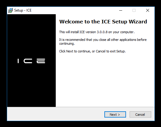
ICE latest release version can be downloaded from the Support Portal.
Follow the instructions of the Set up wizard for the installation on your computer :
2.4. License installation
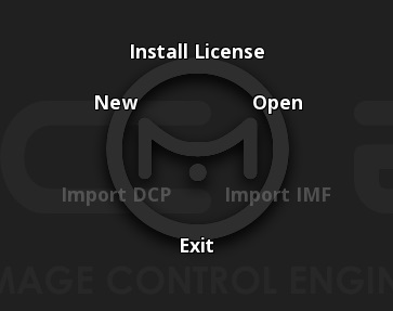
After having installed ICE, you need to launch the software.
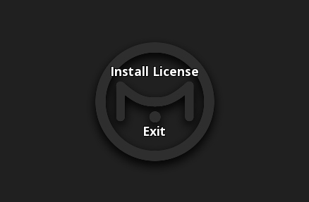
Select the "Install License" button.
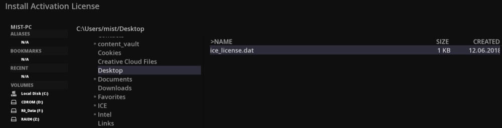
From support@marquise-tech.com , you should have received two files: ice_license.dat and ice.lic.
Sometimes, for a special purpose, these files have different names, you just need to rename them like this.
Installing Primary License for ICE
First step, you have to import the ice_license.dat file.
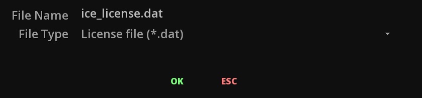
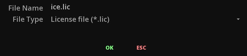
You need to browse the file system where you have stored the licenses. It is easier to find by to setting the correct ".dat" filter in the "File Type" line:
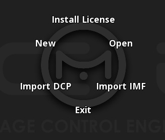
Should the import of the license worked fine, new functions will appear in the starting menu:
Installing Auxiliary License for ICE
The Auxiliary License needs to be imported as well, so select again “Install License” button to to install the ice.lic file:
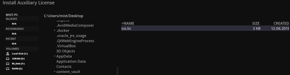
Again browse the file system where you have stored the licenses, and select “.lic” in the file type for retrieving the file.
Now, you have your software correctly activated.
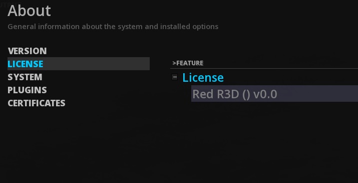
You can check your license and plugins by pressing F12 (About) or by pressing ctrl + right click on the viewer, when a project is open.
3. GETTING STARTED
This section covers high level information about ICE, and in particular:
-
ICE User Interface Structure
-
Interface Basics
3.1. Software Organization
ICE is built around the TimeLine. This backbone is the principal module, from where all the features to achieve QC are accessible.
The secondary module is the Project Management.
3.1.1. Modules
This structure has been specially designed to be as efficient as possible to support long hours of work.
A module in ICE is displayed on the full screen of the user interface. Each module interface differs from the others.
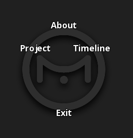
Each module can be accessed from any other module of the application using either keyboard shortcuts or the Module Radial Menu.
-
To access Project press F1
-
To access TimeLine press F3
3.2. Overview of the Project Module
In ICE a project designates a whole structure of directories and files that all together make up the project. The project can be then seen as a shell for various objects that you work with or work on, including assets (video, audio, timed text) and metadata.
Managing the content to playback per project is necessary when you work with component based media, and it allows ICE to support supplemental packages and multiple compositions when playing back DCP and IMF content. The general hierarchy of a project is based on various key elements that are used while working on a project. These elements are listed in the table below:
| Project settings |
Parameters that define the project at the top level such as default composition settings, user interface settings, video IO settings, etc. |
| Project media bin |
The Project media bin references media before it can be used in a composition. It is accessible from the Media tab of the the Command Panel . |
| Compositions |
Each composition is an actual timeline with video and audio capabilities. Any playback will be done within a composition. |
| Various metadata |
Other metadata stored in the project. |
The Project Module is the first module to appear when starting ICE: you will have the choice to open an existing Project, or to create a new one.
In this module are set the parameters for the project, like its properties.
This is also the place where you can set user interface preferences or select a control panel.
Project parameters can always be modified at a later moment, as you work.
This module is detailed under the chapter Project.
3.3. Overview of the TimeLine Module
The TimeLine module is the most important module of ICE. From there all the necessary tools such as the editing timeline, conforming, primary color grading, calibration, color analysis and playback functions are available.
This is also from this module that all the mastering capabilities and export of deliverables are available.
The TimeLine Module workspace is composed of different elements:
-
The Menu Bar
-
The Command Panel
-
The Image Viewport
-
The Timeline
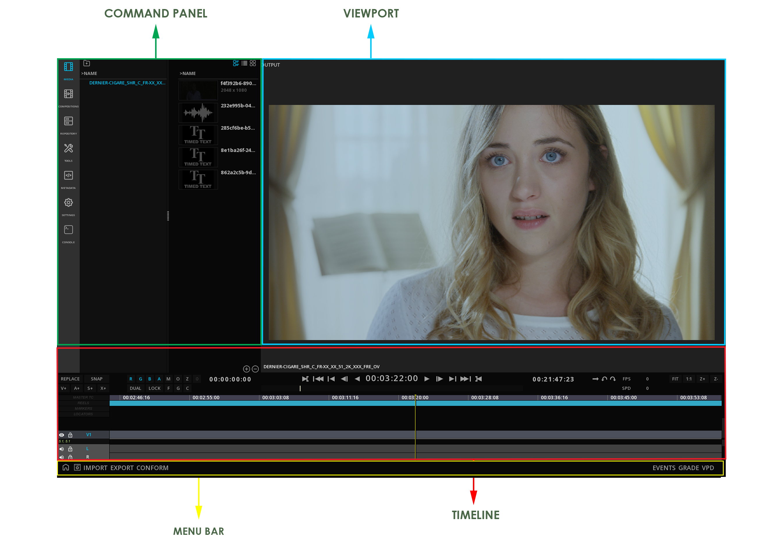
3.3.1. The Menu bar

This menu bar gives access to various capabilities of ICE, related to content management or specific features.
Content management
| COMMAND |
Open / close the Command Panel |
| NEW |
Create a new composition for the Project |
| LOAD |
Load an existing composition on the timeline |
| SAVE |
Save the current composition |
| IMPORT |
Import metadata files (EDL, cutting list, color decision list, QC report, etc.), as well as content packages (DCP, IMF) |
| EXPORT |
Export metadata files (EDL, cutting list, etc.) and reports |
| CONFORM |
Access the Conforming panel |
Features
| AUDIO |
Access Audio parameters |
| EVENTS |
Show / hide the Events Viewer |
| GRADE |
Access to Source Color information |
| VPD |
Access to Video Pipeline Diagram |
3.3.2. The Command Panel
The Command Panel gives access to the assets of a project (media, compositions, metadata) as well as some tools for working with those assets.
From there you will also be able to import and manage the media for the project.
Accessing the Command Panel
By default on opening of a new project the Command Panel is displayed. You can hide it using the COMMAND button on the Menu Bar of the TimeLine:

3.3.3. The Image Viewport
The Viewport layout and capabilities are detailed in the chapter VIEWPORT
3.3.4. The Timeline
The TimeLine behavior is detailed in the chapter TIMELINE.
3.4. Interface Basics
Whatever the module or sub-module you are in, the following interface displays can be met.
3.4.1. Cursors
ICE mouse cursor changes appearance if an action with the mouse is possible:
|
Cursor in normal mode |
|
Possibility to move horizontally an interface element |
|
Possibility to move vertically an interface element |
|
Possibility to extend or resize and interface element |
|
Cursor in move mode |
|
Possibility to set an IN point (in the timeline) |
|
Possibility to set an OUT point (in the timeline) or to extend a clip duration (from the last frame of the clip) |
|
Cursor in trim mode |
|
Indicates that the application is busy performing an operation |


3.4.2. Contextual Menus
A contextual menu is a menu in a graphical user interface (GUI) that appears upon user interaction, such as a right-click. This menu offer a selected set of choices that are available in the current state, or context, of the application.
The Contextual Menus are accessible from every module of ICE, at the current mouse cursor location.
|
Calling a contextual menu when mouse cursor is located on a specific panel or interface element is not always possible. In that particular case, move the cursor to the nearest empty part of the user interface to be able to call the desired Menu. |
ICE uses two different contextual Menus: Radial Menu and Drop-down Menus.
3.4.3. Dialogue Windows
Dialogue windows are represented by large rectangles opening over the module you are in.
They are accessible using interface buttons.
Dialogues windows can have several tabs and sometimes sub-tabs where the user can set different parameters.
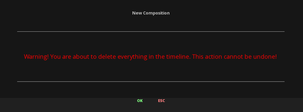
3.4.4. Warning Messages
Warning messages can appear in the different modules of ICE.
These messages interrupt the current work, in order to inform the user about a critical path.
Warning messages always require an action from the user : press OK to continue or ESC to cancel.
3.4.5. Keyboard Shortcuts - Help
A lot of keyboard shortcuts are available in ICE.
-
Press the keyboard H key to display the Shortcuts List available for the current Module (available from the TimeLine module only)
A recapitulation of the available Keyboards Shortcuts for ICE is available in Appendix Keyboard Shortcuts.
3.5. Starting ICE
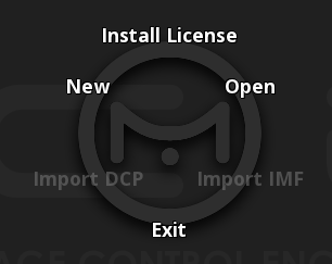
On opening, ICE displays a Radial Menu:

-
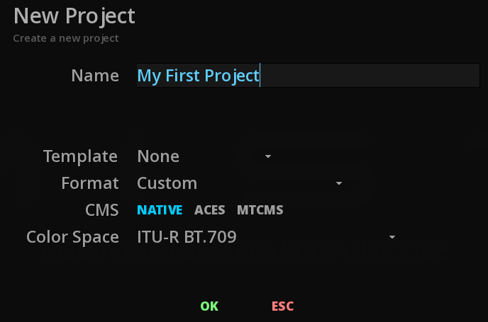
From the menu choose New
The New Project window appears.
-
Add a name and select your settings then click OK
Details about the settings can be found in the Project Management chapter.
The new project opens on an empty TimeLine.
Details about the TimeLine can be found in the TimeLine chapter.

4. PROJECT MANAGEMENT
4.1. Managing Projects
When the application is started, it opens on the Start menu, allowing to either create a new project or opening an existing one.
This Start Menu also permit to exit the application’s session.
The Import shortcuts available are described in the sections DCP Import and IMF Import.
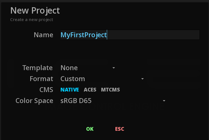
4.1.1. Creating a New Project
-
To create a new project choose New on the Module Radial Menu.
-
Click in the text fields to edit it and type your project information:
|
The following characters are forbidden: |
-
Confirm with [OK] or cancel with Esc.
|
Some basic settings for the project can be chosen from this panel, however the full list of settings are managed from the Project Module. Detailed information about these settings are given in the following sections. |
Once the new project is created, the application switches to the TimeLine module.
4.1.2. Opening an existing Project
-
On the Start Menu, select Open.
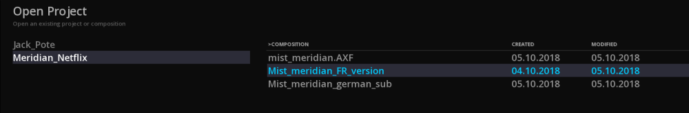
On the left side of the panel the list of all the projects is displayed.
On the right side are indicated the list of all the compositions saved for the selected project.
-
Select the project or the composition diectly and click [OK].
-
A double click on the project will open the last saved composition.
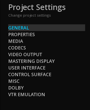
4.2. Project Settings
You can modify the Project settings at anytime. The settings chosen will not affect the project’s compositions, it will only assign defaults parameters to the new compositions created.
-
To modify the Project settings, use the Modul Radial Menu Ctrl+right-click or press F1.
The Project Manager appears in a panel, composed of different tabs:
| General |
General information of the project (e.g. Production company, EIDR, ISAN etc) |
| Properties |
Set the properties and type of the project. |
| Media |
Manage the default media settings. |
| Video Output |
Configure the video output settings of the Video I/O board (e.g. Bluefish444 or AJA). |
| Mastering Display |
Setup the communication with the Reference Monitor. |
| User Interface |
Set user interface preferences. |
| Control Surface |
Connect and setup an existing control surface. |
| Misc |
All the miscellaneous settings like the auto-save setting. |
| Dolby Vision |
Setup the properties of the CMU device. |
| VTR Emulation |
Configure settings to turn ICE in a virtual telecine. |
To leave the Project settings, click OK to go back to the TimeLine.
4.2.1. General Settings
For all projects, it is possible to enter additional information or metadata that can be used as reference information to identify a project:
Insert custom information like Production Company, Director’s name, etc.
-
Click on the edit field and type desired information.
4.2.2. Properties
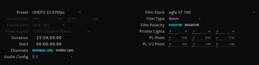
In the Properties tab, set the default dimensions, frame rate or duration for all new compositions in the project.
Each new Composition of the project will be created with these parameters.
|
The settings of a particular composition can be modified at any time, see Composition Settings chapter. |
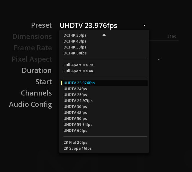
Preset
There is is different output format available as presets:
-
Select the desired preset to set automatically the dimensions, the frame rates and the pixel aspect of the media.
Custom Output format
To define a custom format, select Custom in the Preset drop-down menu, and enter the desired format, frame rate and pixel aspect:
Dimensions
-
Click on the width digits to edit the text and enter the desired value.
-
Press tab to edit the height digits.
-
Finish with enter to save the new dimensions.
You can also change the dimensions by navigating in the cyan bar by dragging the slider one way or the other.
Frame rate
Choose if the project will be played in 24, 25, 29.97 or 30 frames per second. It is important to bear in mind the destination of the final result when setting the frame rate, as it will affect the playback speed.

Pixel Aspect
Select the desired aspect ratio of the Custom project size: 4/3, 16/9, or any other ratio from 1.00:1 to 4.00:1.

Duration
By default, the composition duration is set on 24h.
-
To change the project composition duration, click on the edit field and enter the desired composition duration for the project.
Start
It is possible to set the beginning of the composition (the start) at a specific TimeCode.
By default, the Start is set on 00:00:00:00.
|
This setting affects the current composition only. To modify the Start TC for all new compositions in the project, see Default Start. |
Channels
-
Choose if your project is a Stereo3D project or a normal 2D one. By default, the project is set in Normnal 2D.
Audio config
Allows you to choose a default audio configuration for all new compositions in the project.
Digital Intermediate settings
The following settings are useful only when working from film stock.
Film Stock
If you are working from film then select the stock type via the drop-down menu.
Film Type
Setting a Film type will define how the TimeLine is calculated in Feet + Frames (please refer to the chapter Changing the Timebase display).
Available film types are: 8mm and super 8mm, 16mm, 35mm (2, 3, 4 or 8 perforations) and 65mm (5, 8, 12 or 15 perforations).
Film Polarity
Click on the film polarity in use. The selected one is highlighted in cyan.
Printer Lights
Set the printer to obtain balance for color and density of the stock film. PL Point and PL 1/2 Point allow to refine the values more accurately.
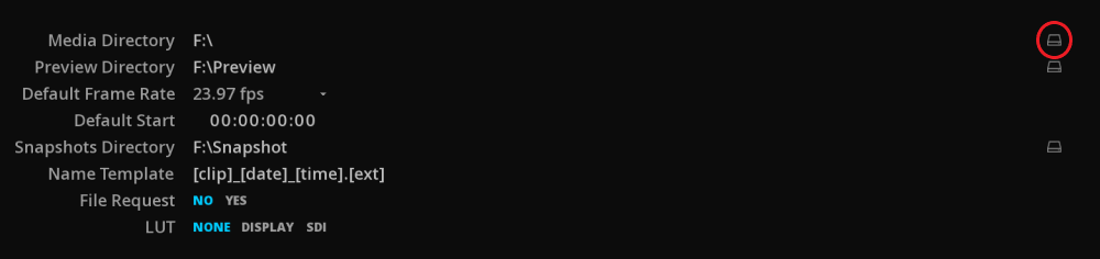
4.2.3. Media
Media Directory
-
The Media Directory allows to define a default location for all media for this project.
|
When you extract the essence of a DCP package, this is also where it is stored. |
Preview Directory
Choose where to store the video thumbnails (media preview) automatically generated when a video content is referenced in a project. By default, htex are stored in the Project directory.
Default frame rate
Some image sequences (e.g. DPX) do not carry frame rate information. In such cases, it is necessary to define a frame rate for this content.
|
Choose a frame rate from the drop-down menu for your image sequence before importing media into the library. |
4.2.4. Codecs
This tab allows you to set the parameters when working with JPEG2000. Depending on the performances of your workstation you can choose to use CPU or GPU power.
In CPU mode, you can also defines the maximum number of CPU threads engaged in the encoding or decoding process.
|
CPU encoding: the number of threads varies with the available shared memory. |
4.2.5. Video Output
In this panel, you can select the properties of the signal that you wish to output.
Once the workstation has been properly connected to a display device (i.e. A DCI compliant projector or a SDI reference monitor), you can setup the video output of your project to obtain the appropriate signal on your device.
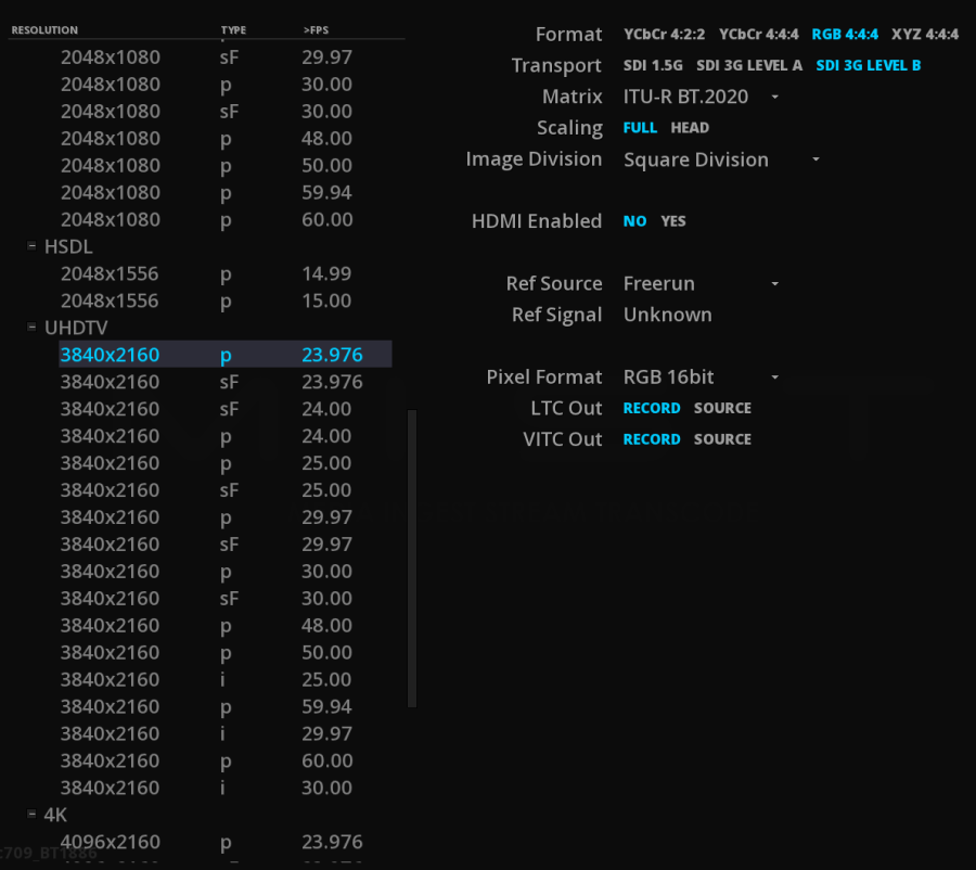
|
Resolutions displayed in the list are relative to the formats supported and delivered by the I/O card. Basics drivers are installed with the application. The |
|
The Video output setting in the Project only defines the output through the video IO card. There is no relation with the project / compositions output properties. |
4.2.6. Mastering Display
This tab allows you to configure the communication between your Reference monitor and the application: the ST-2086 metadata selected in the Mastering Display of the COMPOSITION SETTINGS can be automatically sent to the Reference monitor, allowing to configure it accordingly and avoid the operator to use the monitor’s manual menu.
The following monitors can be remote controlled:
-
Canon HDR 4K monitors
-
Eizo HDR 4K monitors
-
TVLogic HDR 4K monitors
Eizo CG-3145 PROMINENCE
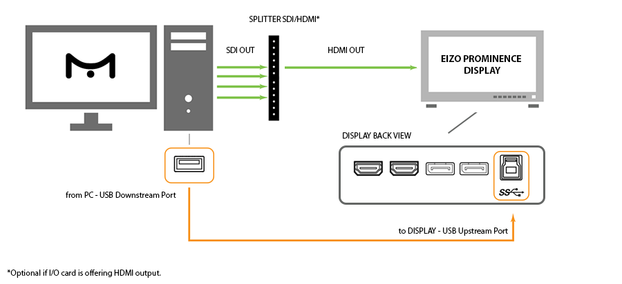
To physically establish the communication between a EIZO Prominence monitor and your workstation, you need to connect a USB cable between the USB downstream port of the PC and the USB upstream port of the monitor before launching the software. The USB hub function is set up automatically upon connection of the USB cable.
When the application is lauches, it takes control of the settings of the EIZO monitor. Each time a composition is loaded, the selected mastering display parameters are communicated to the EIZO monitor, which is automatically configured accordingly.
A change of mastering display preset will refresh the monitor. The new parameters used are indicated temporarily on the monitor.
TVLogic LUM-310R
To establish the communication between a TVLogic LUM-310R monitor and your workstation:

-
Get a DB9 Female to RJ45 Male cable.
-
Connect the cable from the RS-232 port of your computer to the RS-422 IN port of the TVLogic display.
-
Open the
.cfgfile for your application in the directory C:\Users\$SessionName$\AppData\Roaming\Marquise Technologies\session. -
Add the following lines between <MTSessionConfig> and the </MTSessionConfig> tag:
<DisplayMonitorConfigList>
    <DisplayMonitorConfig id="tvlogic">
        <CommPort>COM1</CommPort>
        <DeviceId>1</DeviceId>
    </DisplayMonitorConfig>
</DisplayMonitorConfigList>
The CommPort number to indicate depends on the CommPort available on your system.
The DeviceId number must be the same as indicated in the monitor’s menu settings in the GPI tab / Monitor ID. Change one or the other accordingly. The default DeviceId is number 1.
Save the file before leaving.
4.2.7. User interface
Select your preferences for the user interface:
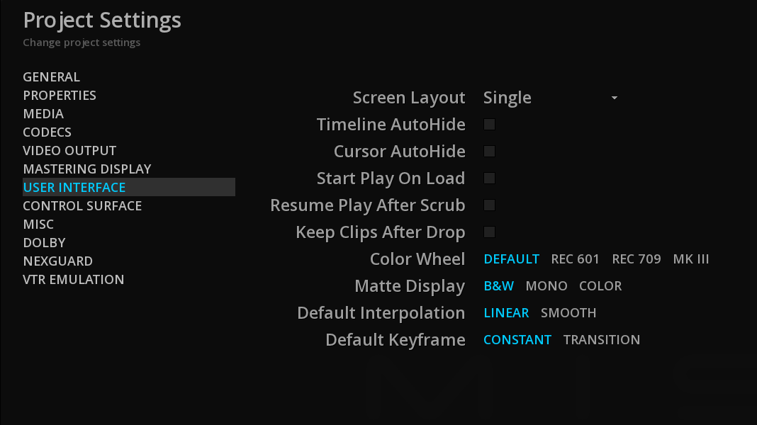
| Screen Layout |
Allows you to display the User Interface on 1 or 2 monitors (Dual). |
|
you must restart the software to apply this change. |
| Timeline Auto-Hide |
automatically hides the Timeline during playback |
| Cursor Auto-Hide |
automatically hides the mouse cursor during playback |
| Start play on Load |
starts automatically the playback of the content loaded on the timeline. |
| Resume Play after Scrub |
resumes the playback after a scrub of the playhead with the mouse. |
| Keep Clips after Drops |
keeps the clips attached to the mouse when performing a Drag and Drop on the timeline. This is useful when adding the same clip several times on the timeline. |
| Color Wheel |
Allows you to choose the orientation of your color-grading wheels |
| Default Keyframe |
Selects the default Keyframe and interpolation settings based on your needs. |
4.2.8. Control Surface
When using a control panel, this is where you can connect and configure it.
The Tangent Devices panels are supported.
-
Select the desired device from the drop-down menu.
|
Please be sure to have install the control panel’s drivers before. |
4.2.10. Dolby
This sections defines the default settings for Dolby technologies.
Dolby Vision
Allows you to configure Dolby Vision settings.
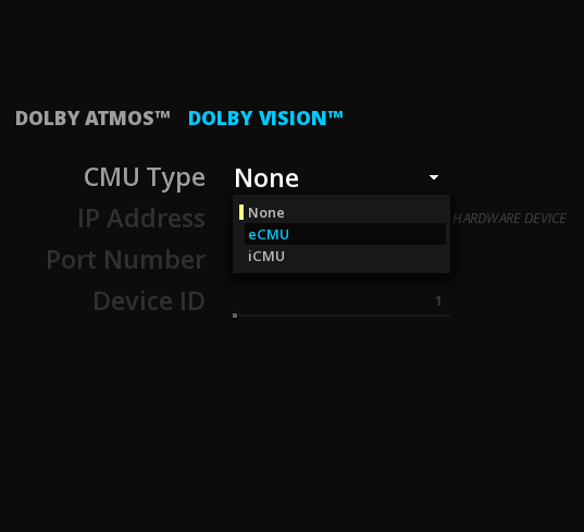
| CMU Type |
Select if you want to use Dolby iCMU (internal CMU, aka Software CMU) or a Dolby eCMU (external CMU device). |
If eCMU is selected, then enter the connection information between your workstation and the eCMU:
| IP Address |
Type the IP address of the connected eCMU. |
| Port number |
Type the port number of the connected eCMU. |
| Device ID |
Move the slider to change the device ID of the connected eCMU or double-click on the device number to edit it. |
See also Set up of the CMU in the HDR chapter.
5. IMPORTING MEDIA
ICE allows to import a large variety of media:
flat files, packages like DCP, IMF or iTunes, image sequences, PDF and XML files in sidecar, EDLs, camera magazines, etc.
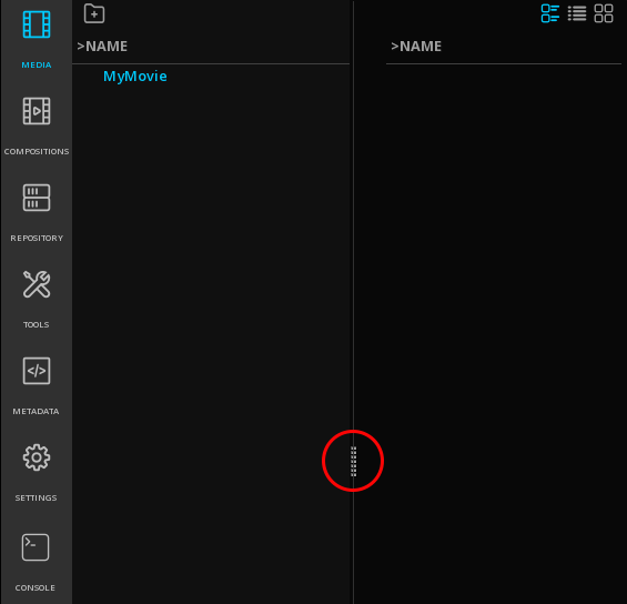
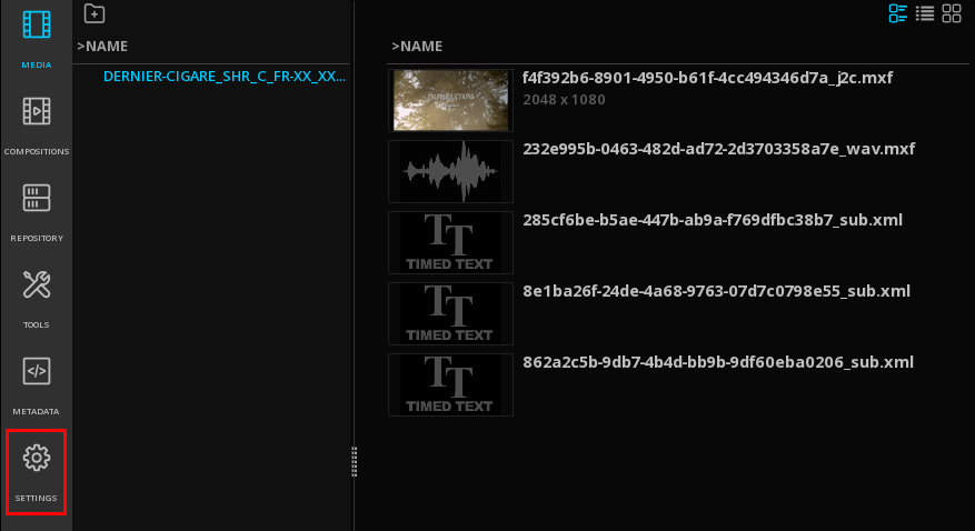
In ICE, media are managed in the Media tab of the Command Panel.
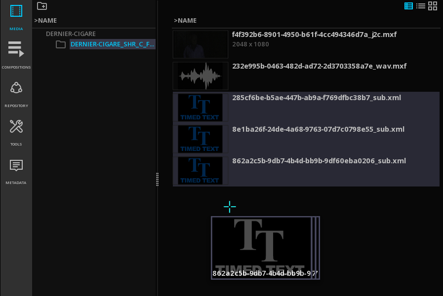
5.1. Media Tab
The Media tab is where the essences for a specific project are manually or automatically referenced from disks or a SAN.
The essences can be any type of video, audio, or subtitles files.
The Media Tab also permits the organization of the content for a project. From there assets can be selected to get loaded on the timeline.
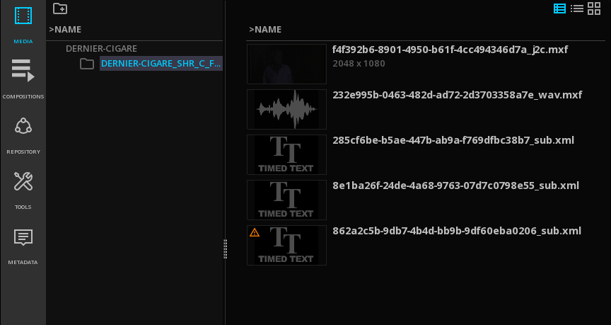
The MEDIA tab is composed of 2 columns: on the left, the folder tree, and on the right the related content, like in a standard file browser interface.
-
To adjust the width of the columns use the vertical slider :
5.1.1. Organizing the Project Media
You can create folders to organize the project media according to your needs.
-
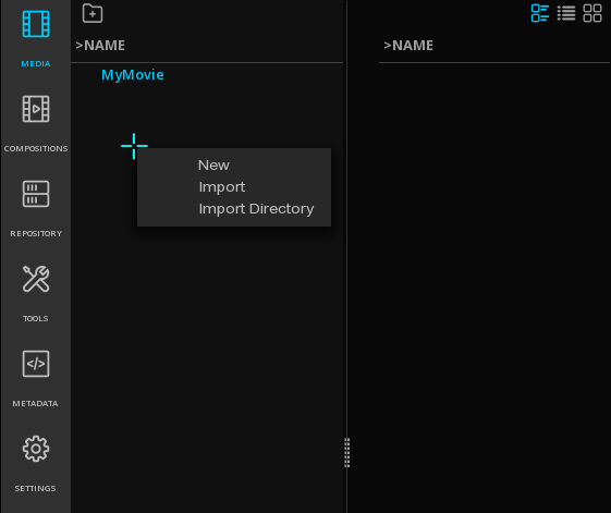
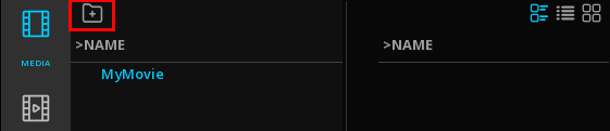
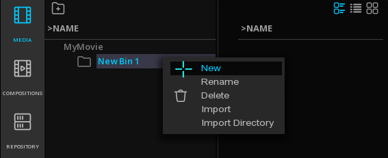
to add a folder, position the mouse in the left column and press mouse’s right button. Choose New from the drop-down menu:
Alternatively you can use the icon "add folder":
|
when adding other folders at root level, make sure that the root project is selected (highlighted in blue) and not a folder. |
-
to add a sub-folder, select the desired folder and press mouse’s right button. Choose New from the drop-down menu:
-
to delete a folder or a sub-folder, select the desired folder and press mouse’s right button. Choose Delete from the drop-down menu.
-
to rename a folder or a sub-folder, select the desired folder and press mouse’s right button. Choose Rename from the drop-down menu.
5.2. Import of Media
There is two ways for importing media for a project:
-
Drag & Drop
-
Import function
5.2.1. Drag & Drop files from Windows' file system
Drag & Drop from Windows' file system allows you to easily import flat files, packages (DCP, IMF, iTunes, etc..), image sequences, camera magazines, compositions, sidecars files, etc. as well as entire directories.
-
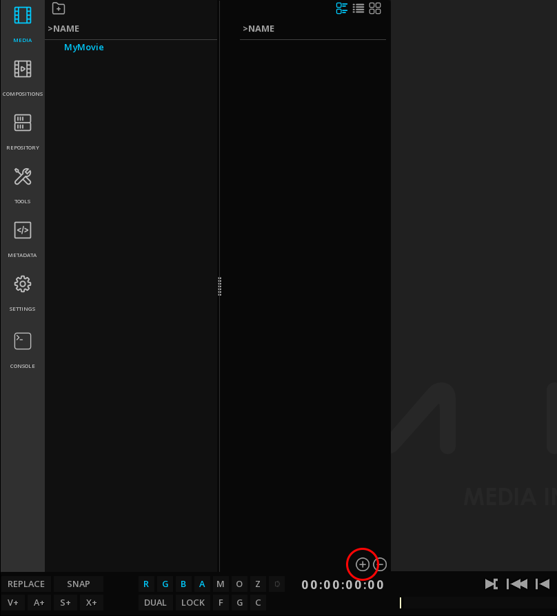
Hit the Windows key or press the button + at the bottom right of the panel to display the Windows file browser.
-
Select your files and drop them anywhere in the application’s window.
Once the media are properly referenced, they are displayed in the Media tab.
-
To import content into a specific folder of the project media, first select the desired folder prior to drag & drop the content.
Drag & Drop sequences
To import image sequences like DPX or TIFF drag & drop the first image of the sequence and the full sequence will be automatically imported.
|
Because there is no information about frame rates in DPX or TIFF images, first set the correct frame rate in the Properties of the Project. |
5.2.2. Import Panel
The Import panel is an internal browser that has the capability of understanding complex media files and packages.
This is also the function you will use to import specific metadata files like EDLs, Dolby Vision .mdf or QC reports in XML.
Access import from the Media tab
-
position the mouse in the left column and press mouse’s right button. Choose Import from the drop-down menu:
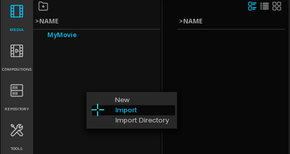
-
Alternatively double-click on an empty area of the left column
-
To import content into a specific folder of the project media, first select the desired folder prior to import the content.
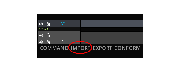
Access from the IMPORT button
Click on the IMPORT button on the menu bar to display the Import panel.
Import panel
The Import panel is composed of 2 areas:
The left column, used for quickly navigating through the physical files volumes the system is connected to.
Bookmarks and Aliases are also displayed there.
The folder tree column, showing folders' organization within a volume.
|
When a package like a DCP or an IMF is selected, the CPLs and the important metadata of the package are automatically displayed : 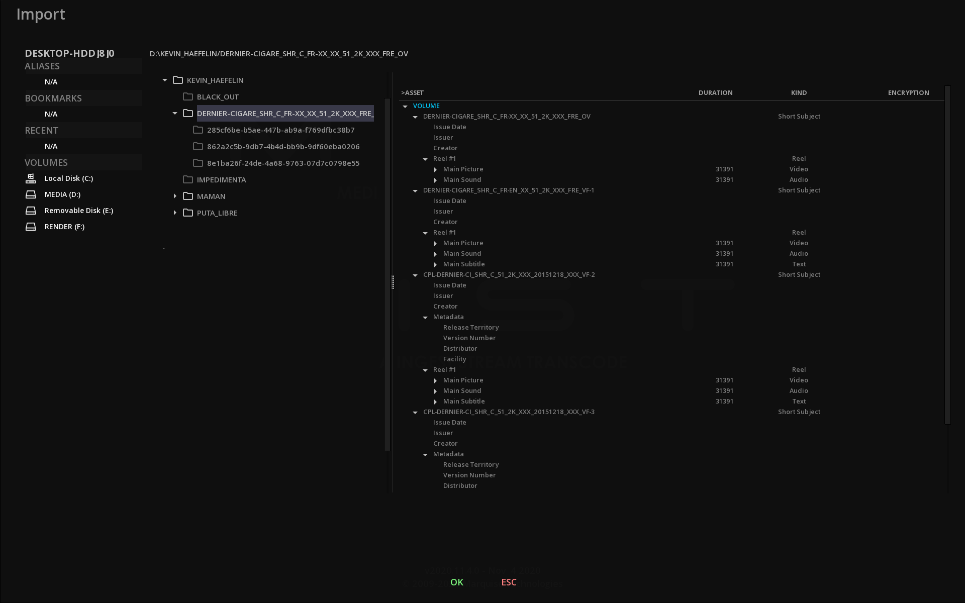
|
In order to ease the navigation, you can display only a specific file type.
-
Click on the file type to open the drop-down menu:
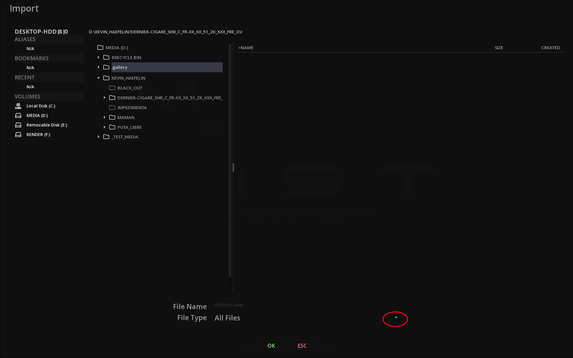
-
Select the desired type of file from the list:

-
Validate the import using OK.
5.2.3. Delete Media
-
to delete a media, select the desired clip and press the button - at the bottom right of the Command Panel.
Alternatively, when the clip is selected, you can press the mouse’s right button. Choose Delete from the drop-down menu.
|
Deleting a media in the Media tab will remove it from the Project media bin and will not physically delete the file. |
5.3. Import of Directory
It is possible to import an entire directory in the project media bin: the source directory organization with the folders and subfolers and their related files is reproduced in the media bin.
This functionality is particulary useful when importing complex folder’s organisation like a camera magazine or DPX sequences organised in reels.
-
To import a Directory, position the mouse in the left column and press mouse’s right button. Choose Import Directory from the drop-down menu:
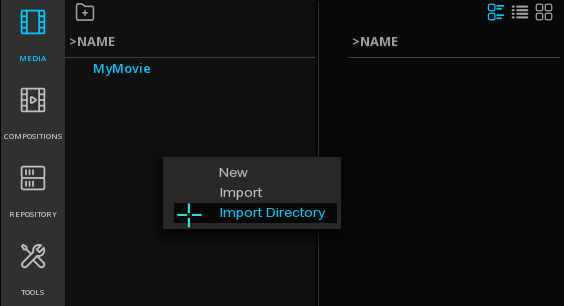
Navigate in the file browser to the desired directory, and validate the import using OK.
5.4. Relink Media
When a media referenced in a project has been moved from its original physical location, the application cannot access it and it is no longer possible to work with it.
In this case, a warning is displayed on the clip:
It is then necessary to proceed to a manual relink of the path to the files.
-
right-click on the clip in the Media tab to display the drop-down menu.
-
Browse the file system to the new location of the file
-
Click OK to validate
Your media is now relinked.
5.5. Direct Playback from the Media tab
-
A double click on a media will automatically load the content on the timeline.
-
To start automatically the playback of the content loaded on the timeline, enables the option Start play on Load in the Project Settings, User interface
-
To load manually the media, refers to section Adding clips to a composition
-
to start the playback of an IMF or DCP package, see the Composition tab below.
You can also right-click on a clip in the library to display the drop-down menu options:
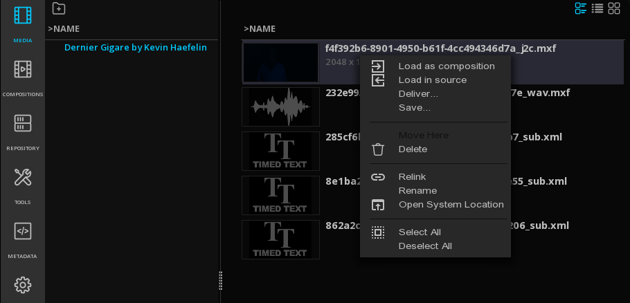
| Load as Composition |
Load the clip on the timeline in a new Composition |
| Load as Source |
Load the clip in the Source Viewport |
| Save… |
Save the media metadata in EBU Core XML |
| Delete |
Delete the clip from the project media bin |
| Relink |
To relink a media |
| Open System Location |
Opens the Windows’s file browser to the physical location of the media |
| Select All |
Select all the clips in the current directory |
| Deselect All |
Deselect all the clips in the current directory |
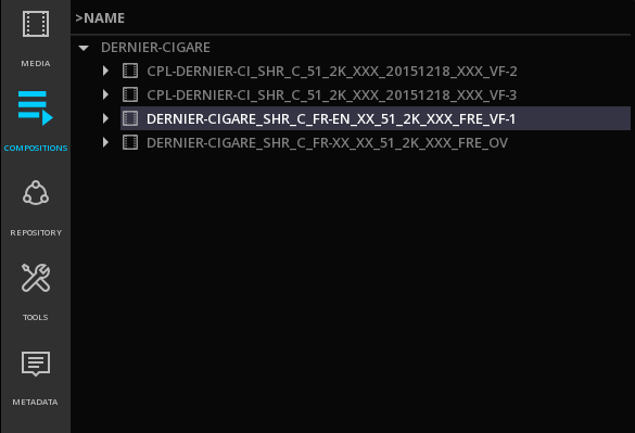
5.6. Compositions Tab
This tab displays all the compositions available in the project, whatever their type is: CPLs of an IMF or a DCP package as well as project’s compositions.
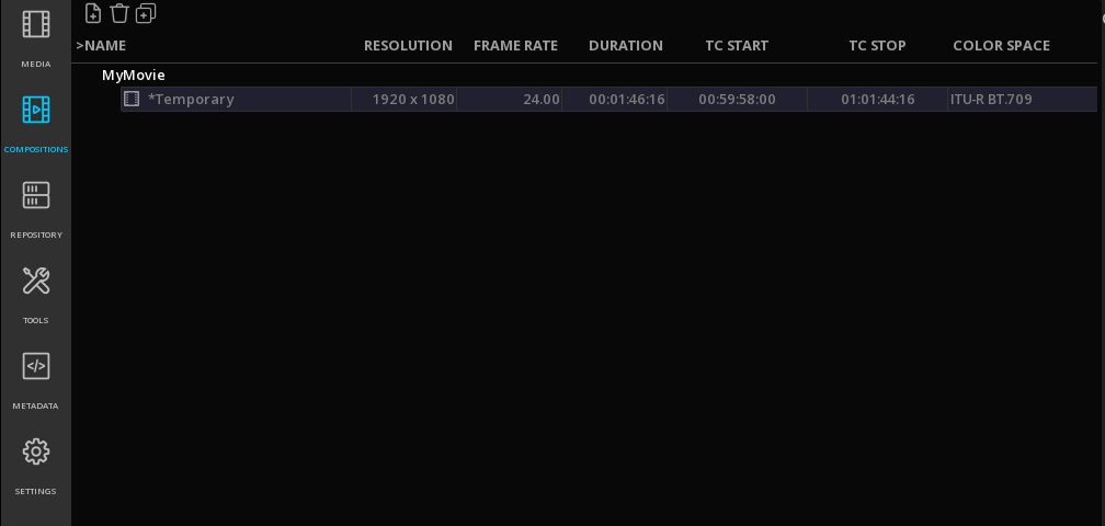
By default, when a media imported in the Media bin is played, a Temporary composition is automatically created. This composition will be replaced by a new temporary composition if another media is chosen to be played, unless it is manually saved.
All the compositions saved for a project will be also accessible from this tab.
When importing a DCP or an IMF package, CPLs are listed as compositions:

5.6.1. Playback of the Composition
-
A double click on a Composition will automatically load all the assets referenced in the composition on the timeline.
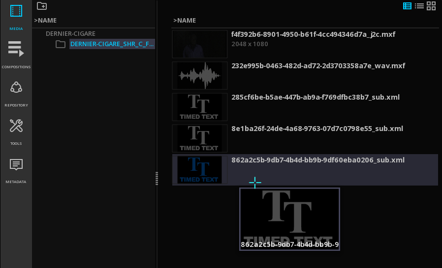
5.6.2. Sidecar assets
When a package contains SideCar files, they are displayed in the list Sidecar Assets.
-
To open a SideCar asset double click on it. If Windows system recognizes the file type, the associated application will be automatically launched.
5.6.3. Processing Graphs
OPLs present in an IMF package are listed under the Processing Graphs list.
Read more on Compositions
5.7. Inspecting the media
The Metadata Tab of the Command Panel allows the inspection of the metadata embedded in a file: COMPOSITION, CLIP, STATIC and DYNAMIC metadata.
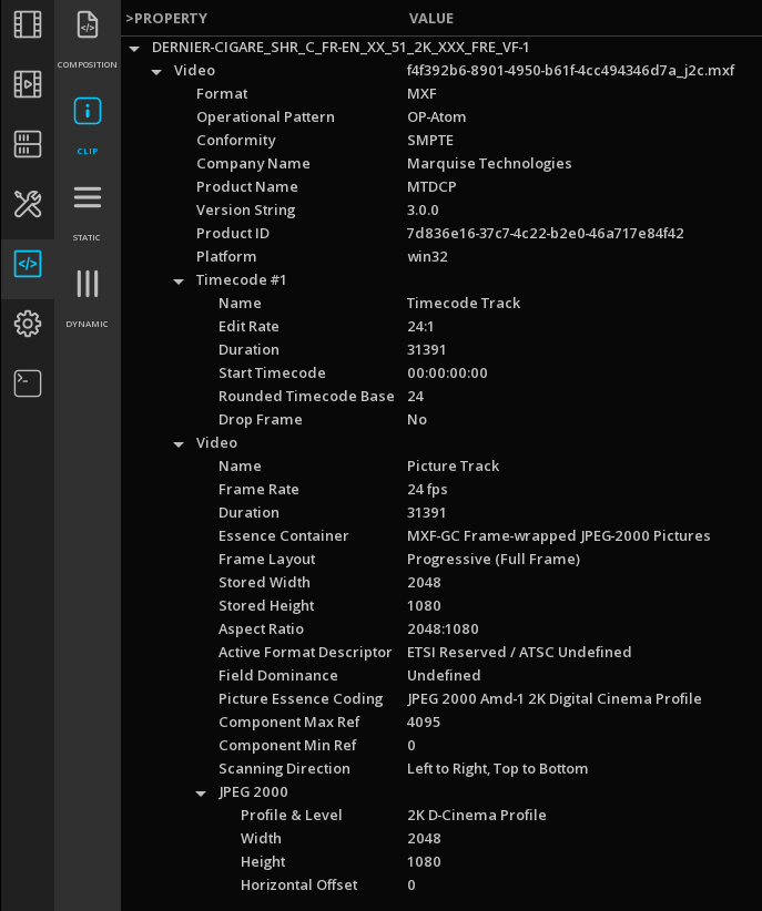
| COMPOSITION |
metadata of the CPL or the media manifest |
| CLIP |
thechnical metada of the clip |
| STATIC |
technical or descriptive metadata valid for the entire clip |
| DYNAMIC |
technical or descriptive metadata valid for a frame or a scene. |
The metadata displayed are those of the file loaded on the timeline. When multiple files are present, the metadata are displayed for the content on the active layers at the playhead location.
|
To inspect the metadata of a clip in the media tab, without modifying the current composition on the timeline, you can load it in the Source Viewport. |
6. THE TIMELINE
The TimeLine is the core feature of ICE.
From the TimeLine, you have access to a variety of tools allowing to play and QC any type of content.
In this chapter you will learn the following:
-
Basics for the timeline
-
How to create new compositions
-
How to add clips to the compositions
-
How to load and save compositions
-
How to use the Event Viewer
6.1. Definitions
Below you will have an overview of the vocabulary frequently used in the Timeline section :
| Project |
A project is a structure that is made of several compositions. |
| Composition |
A composition is a structure made of different sorts of media assets: video, audio and timed text (e.g. close captions or subtitles). The metadata associated to the assets are also part of the composition. |
| Layer |
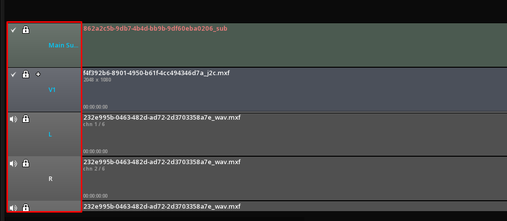
A layer is a placeholder for tracks. The number of tracks depends on the layer category, audio, video or other. |
| Video Layer |
A video layer is made of 2 tracks: V1 (also called the A-Roll) is the main video track of the layer. V2 (also called the B-Roll) is the secondary video track of the layer is generally used only when transitions are involved. |
| Audio Layer |
An audio layer is made of one or several tracks, depending on the audio configuration. The audio configuration specifies the number of audible tracks, usually assigned to individual speakers in a spatial configuration. The following soundfields among others are supported: Mono, Stereo, 5.1, 6.1, 7.1. |
| Track |
A track is a placeholder for segments. Segments can be moved within the track, trimmed, slid (Slide operation) or slipped (Slip operation). |
| Segment |
A segment is a basic unit of editing. It defines the start and end of a media source (audio, video or subtitles) in time. Transitions (video or audio) are special segments that do not represent any media source but rather blend two other segments (audio and audio or video and video). |
6.2. Image Viewport
The Viewport is the part of the workspace where the image is displayed.
On opening of a project, the Viewport is reduced but you can enlarge it by closing the Command Panel or minimizing the timeline.
6.2.1. Navigate / Pan
To easily navigate in any area of the image, use the pan navigation:
-
Alt + click and maintain left mouse button pressed to move the image in every possible direction.
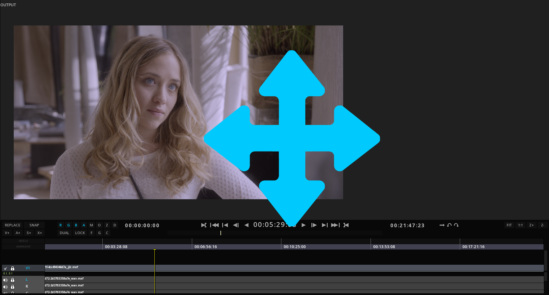
-
Press C to center the image in the Viewport.
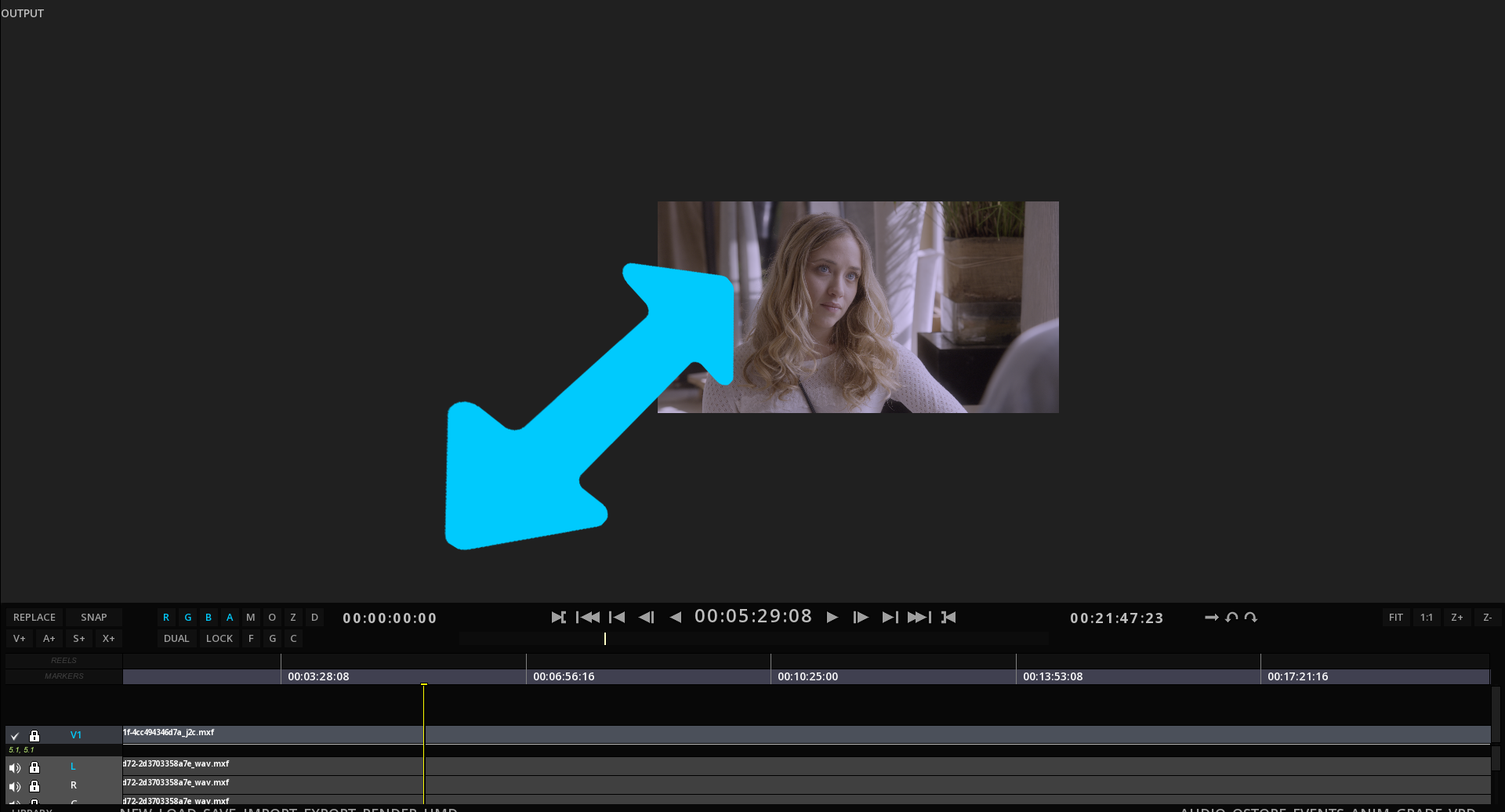
6.2.2. Zoom
To zoom in a specific part of the image:
-
Scroll middle mouse button down to zoom IN, and scroll up to zoom OUT.
6.2.3. Viewport Options
From the GUI
Some controls for the Viewport are directly accessible from the GUI (in addition to keyboard shortcuts).

R |
Show / hide Red channel |
G |
Show / hide Green channel |
B |
Show / hide Blue channel |
A |
Show / hide Alpha channel |
M |
Show / hide Mask |
O |
Show / hide Original image |
Z |
Show / hide Zebra mode |
D |
Show / hide Dynamic Tone Mapping |
F |
Lock Fit Viewport |
G |
Gang the 2 Viewports |
C |
Comparator |
Dual |
Show / Hide Dual Viewport |
Lock |
Lock Viewports playback together |
Guides
Display guide lines on the Image Viewport:
| Camera |
Alt+C to show camera borders (project format) |
| Axis |
Alt+A to display the Viewport axis |
| Safe Frames |
Alt+F to show Action and Title safe areas according to the Active Area chosen. |
| Active Area |
Alt+B to display the borders of the frame as per the frame aspect chosen in the Active Area tab. |
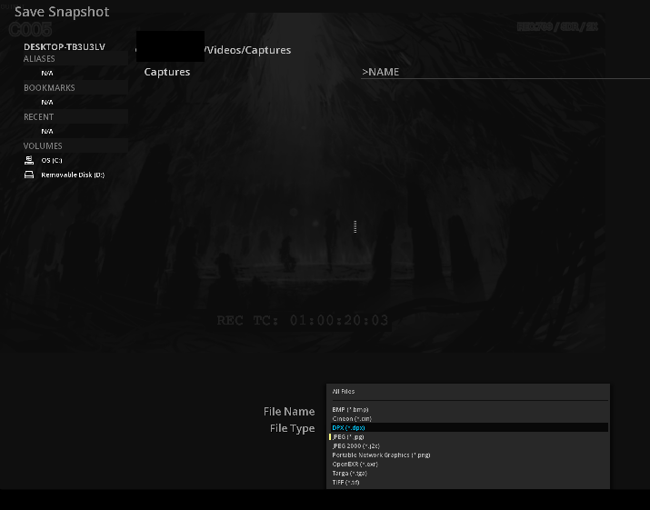
6.2.4. Snapshots
It is possible to capture a snapshot of the content displayed in the viewport.
-
to capture a snapshot, press Ctrl+F12
Settings for the snapshots are located in the Media section of the Project.
It is possible to define automatically the naming convention for your snapshots as well as the directory to save them, or to opt for a manual saving.
You can also add the LUT defined for the GUI or the SDI output.
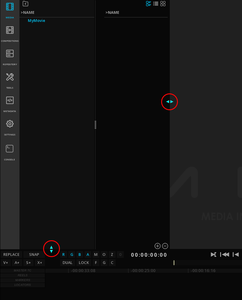
6.3. Dual Viewport
The Dual Viewport allows you to display simultaneously two video tracks for comparison purposes. The two Viewports can also be synchronized together, for an accurate frame matching.
6.3.1. Adding media on the Dual Viewport
To use the Dual Viewport option, it is easier to start with an open project.
-
To open the Dual Viewport, click on DUAL on the TimeLine or use the shortcut Alt+X:

The right Viewport is for the Composition, and the left Viewport is used by the source media.
-
Select the source media from the Command Panel and press Ctrl + double mouse click: it will automatically be placed in the Source Viewport.
|
All kind of file formats can be loaded in the source viewport, including IMF and DCP packages. |
-
To toggle from one Viewport to the other, click on the desired Viewport. The timeline displayed is the one for the Vewport outlined in grey (active viewport).
-
You can also switch from one to the other with the X shortcut.
The navigation management tools in the Viewport remain the same as for Single Viewport on the selected Viewport. Refer to chapter Viewport Manipulations .
6.3.2. Frame matching
It is possible to synchronize the timeline of the source with the one of the composition to do frame matching.
-
Select the viewport you want to use as the reference image, position the playhead on the desired location and click LOCK or press the G key.
Automatically, the second timeline will place and lock the playhead position at the same image number. You can also playback both timelines at the same time.
|
The frame matching depends on the duration of the two timelines. If one is shorter than the other, the last selected image of the shortest timeline will remain frozen. |
6.4. Timeline Basics
The Timeline itself is composed of several parts:
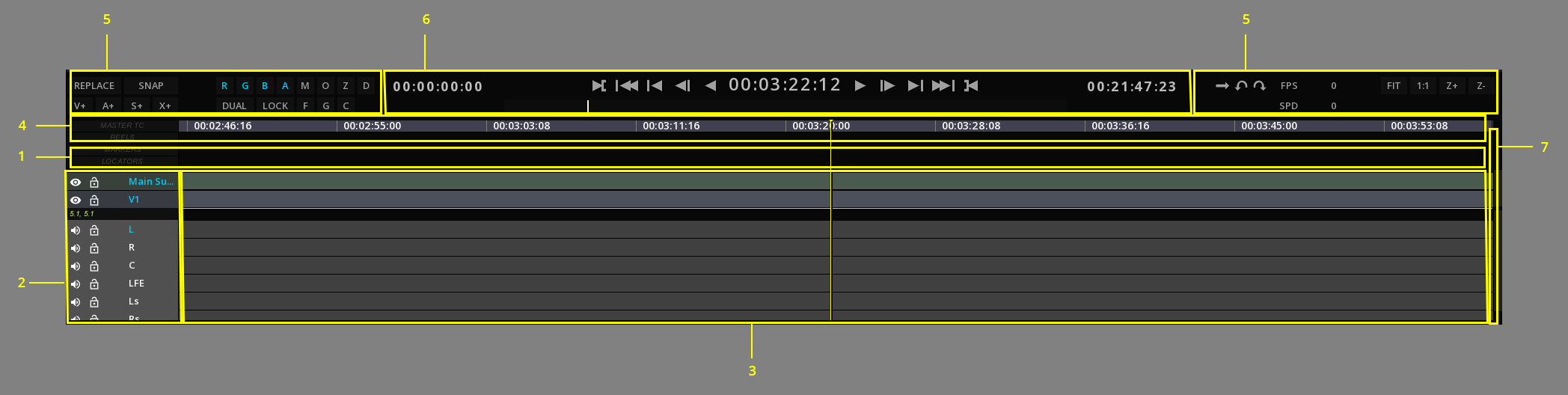
1 |
TimeLine Background |
2 |
Layers Control Box |
3 |
Layers |
4 |
Composition Timescale |
5 |
TimeLine Controls |
6 |
Transport Controls |
7 |
Slider |
6.4.1. Transport Controls
The commands for the Transport controls are the following:

1 |
Composition Start time |
2 |
Mark IN point |
3 |
Go back to first frame |
4 |
Go back last key frame |
5 |
Go back next frame |
6 |
Play backward |
7 |
Time Code at current frame / playhead position |
8 |
Play / Stop |
9 |
Go to next frame |
10 |
Go to next key frame |
11 |
Go to last frame |
12 |
Mark OUT point |
13 |
Composition End time |
14 |
Playback Mode |
6.4.2. TimeLine Controls
Some controls for the timeline are directly accessible from the GUI (in addition to keyboard shortcuts).
6.4.3. PlayBack & Speed information
The user interface displays playback information. It is also possible to change the playback speed on the fly.

6.4.4. Navigating the Timeline
Depending on the length of the composition, you may need to navigate through the composition back and forth, or change the display scale to reveal more or less of it.
Moving around in the Timeline
To move around the timeline without changing the playhead position, is done by using the keyboard and mouse. The following procedure explains how to move the timeline to the left or to the right to reveal the parts that could not be displayed on screen:
-
Press Alt on the keyboard and using the mouse, click the left button and drag the mouse while keeping the left button pressed.
The timeline will be shifted to the left or to the right, revealing the hidden regions.
Zooming the Timeline
You can display the complete timeline or a detailed part of it without changing playhead position by zooming in or out the timeline:
-
To zoom IN our OUT use the hotkeys Ctrl++ / Ctrl+-
-
Alternatively press the buttons Z+ and Z-.

You can also automatically fit the composition in the timeline:
-
To fit the composition in the timeline, use Ctrl+Shift+F or press the FIT button.
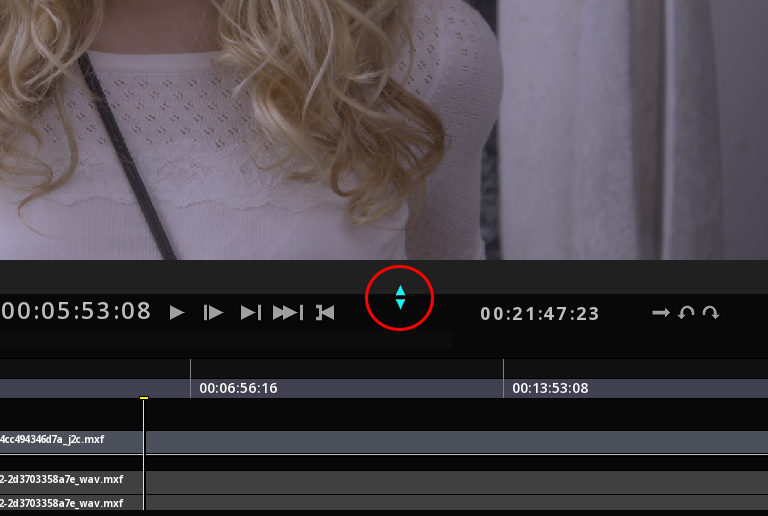
Positioning the Playhead
This vertical yellow line indicates where in the timescale the current frame is located. It is also referred as “Timemarker”.
To center the playhead in the TimeLine, use the hotkey Ctrl+Shift+C.
TimeLine Navigation Shortcuts
To navigate more easily in the timeline some playhead shortcuts are available and detailed in the appendix Shortcuts.
6.4.5. TimeLine Configuration
The TimeLine can be configured to serve your needs depending on the projects you are working on. Possible configurations include:
-
Changing the Timebase
-
Modifying the Layers appearance and manipulating them
-
Manage Layers and create new ones
Changing the Timebase display
The Timebase (or timescale) is by default in time code mode.
It can be modified to display other time codes or frame information.
The Timeline can be displayed in the following modes:
Normal time Code
Feet + Frame
Frame Number
-
You can toggle the Timebase displays using Alt+T.
Timebase display in Time Code:

Timebase display in Feet + Frame:

Timebase display in Frame Number:

Modifying Layers appearance
The layer appearance can be modified to better display the tracks information if needed.
The TimeLine part can be expanded to display more layers:
-
To expand or collapse TimeLine, place the cursor on the top of the time line until it changes appearance and lift up or down.
-
To navigate in the different layers, use the Scroll Bar on the right of the Timeline.
-
To select several layers, press Ctrl + click and pick the desired layers.
-
To select all the layers, press Ctrl+A.
-
To deselect all the layers, press Ctrl+D.
In the user interface the tracks are separated by a "split". It can be moved up and down to reveal more or less of one of the stacks.
This action reveals additional information like the image resolution for the video layer, or the audio channel number for an audio layer.
-
To resize all the layers altogether, select the layers on the Control Box on the left of the TimeLine using Ctrl + click, keep Ctrl pressed and scroll up or down the mouse reel.
Managing Layers
Some managing operations are available for each type of layer.
-
To display the drop down menu for the layers, position the mouse on the Layers Control Box, select the Layer you want to modify and press right-click.
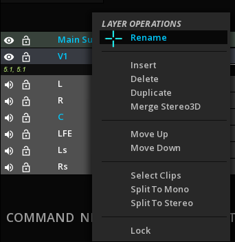
| Rename |
Allows to rename the layer. |
| Insert |
Insert a layer right above. |
| Merge Stereo 3D |
Allows to merge left and right eyes in one track. |
| Delete |
Delete the current layer. Deleting a track removes all clip instances on the track but does not affect source clips available in the library. |
| Lock |
Lock the current layer. |
| Move Up/Down |
Allows to reorder your tracks by moving them up or down. |
| Select Clips |
Selects all the clips in the track chosen. |
| Split |
You can split your audio configuration to mono or stereo tracks |
Layers Manipulation
An important notion when manipulating the Timeline layers is the “Active” layer. This is especially important when editing the clips.
Active layers are labelled in blue:
In order to quickly manipulate the layers, you can use the Timeline Hot Box.
-
Place the mouse cursor on the TimeLine background and press Ctrl + right-click to display the Hot Box for the TimeLine ans select LAYER:
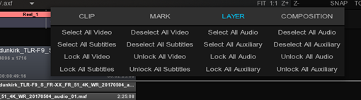
The Hot box provides you with short cuts to select or deselect the different type of layers.
The Layer Control Box also displays important icons:
|
Indicates that the layer is enabled. To change layer status to disabled, click on the icon. |
|
Indicates that the layer is disabled. To change layer status to enabled, click on the icon. |
|
Shortcut to lock the layer. Icon turns red when activated. |


Create new Layers
At any time you can add additional layers to the composition. Layers can be added according to their type, video, audio, etc..
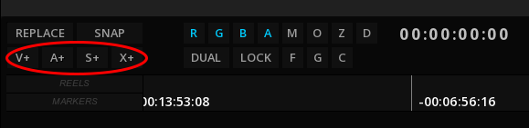
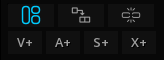
| V+ |
Insert a Video layer on top of all others |
| A+ |
Add an audio layer at the bottom of all others |
| S+ |
Add a timed text layer (for subtitles or closed captioning) on top of the video layers. |
| X+ |
Add an auxiliary track at the bottom of the audio layers. Auxiliary tracks are used to display special metadata tracks like Dolby Atmos, DBox, etc… |
About Auxiliary Tracks
Click X+, to display a drop-down menu and chose the appropriate auxiliary track:
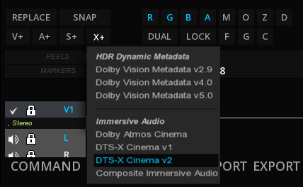
HDR Dynamic Metadata
| Dolby Vision Metadata v2.9 |
use this type for adding a Dolby Vision 2.9 Metadata ISXD track |
| Dolby Vision Metadata v4.0 |
use this type for adding a Dolby Vision 4.0 Metadata ISXD track |
| Dolby Vision Metadata v5.0 |
use this type for adding a Dolby Vision 5.0 Metadata ISXD track |
Immersive Audio
| Dolby Atmos Cinema |
use this type for adding an Atmos track for a DCP package (see DCP with Dolby Atmos) |
| DTS-X Cinema v1/v2 |
use one of these types for adding a DTS-X Cinema immersive audio track for a DCP package. (see DCP with DTS-x) |
| Composite Immersive Audio |
use this type for adding an immersive audio metadata like Dolby Atmos as IAB track for an IMF package. |
6.5. Compositions
Assembling a program from multiple clips is done in a composition. By default every project has a default composition, called “Temporary”. However in a real world project, it is necessary to create multiple compositions for various needs, such as various edits of the same program, etc.
A composition is a structure made of different sorts of media assets: video, audio and timed text (e.g. close captions or subtitles). The metadata associated to the assets are also part of the composition.
It is also definite by a format (width, height, bitdepth, frame rate, sample rate, etc) and a duration.
In addition other composition properties exist such as a marking zone, markers, playheads, etc to help the editing process. Each sort of media is organized into layers: the video layers (located in the video layer stack) and the audio layers (located in the audio layer stack).
Editing of video layers and audio layers can be done separately or jointly.
Layers are composited together in their category (video layers together, audio layers together).
The result of a composition is a video stream and one or more audio streams (one for mono, two for stereo, etc). The rendering of a composition generates a new clip.
In this section, you will learned the following:
-
Adjusting a composition’s duration
-
Managing (Saving, loading) compositions
-
The Composition settings
6.5.1. Composition duration
Composition duration is displayed in light grey over the timescale:
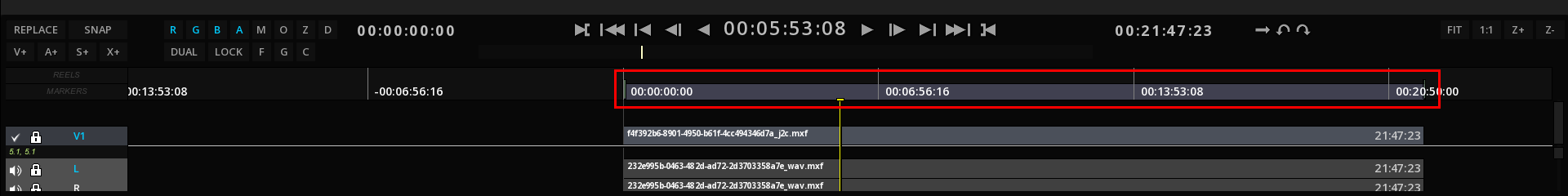
By default, the composition is set on 24h.
The duration of the composition can be adjusted by a simple move (left mouse click and drag) of the small handles at each end of the line.
-
To auto adjust the composition duration to the clips on the timeline, press Alt+Ctrl+F
The Composition can also be manually adjusted by typing values for the beginning and the end of the composition:
-
Click in the Composition Start and / or End in the Shuttle Bar, and type desired values.

The composition is automatically updated with the new duration.
In order to quickly fit the composition, you can also use the Timeline Hot Box:
-
Press Ctrl + right-click on the Timeline itself to display the TimeLine Hot Box and select COMPOSITION. The Hotbox provides you with short cuts to fit the different type of layers of the composition.

|
The duration of the composition affects the playback: if part of a media is outside the composition, it will not be played. |
|
If you drag & drop an IMF or a DCP package containing multiple CPLs, ICE will automatically creates the compositions for each of the CPLs. |
6.5.2. Composition Management
A project can contain an unlimited number of compositions, each of them with a different output format, frame rate or image resolution.
Compositions are reflecting the content of a Timeline. You can save them and reload them.
Start a new composition
-
Click NEW on the bottom of the timeline (left side),
-
or press Ctrl+N
|
this action deletes all previous compositions not saved. |
|
Compositions can only be created but cannot be deleted directly from the application. Deletion of compositions is not available in order to avoid mistakes. However the compositions can be deleted using Window’s file system. |
Save a composition
-
To save a composition, click SAVE on the bottom of the timeline (left side),
-
or press Ctrl+S
Select the desired disk and directory to save your composition.
By default, the composition are saved in Authoring eXchange format (.axf).
Load a saved composition
-
To load a composition, call the Module Radial Menu and select LOAD,
-
or click LOAD on the bottom of the timeline (left side),
-
or press Ctrl+O
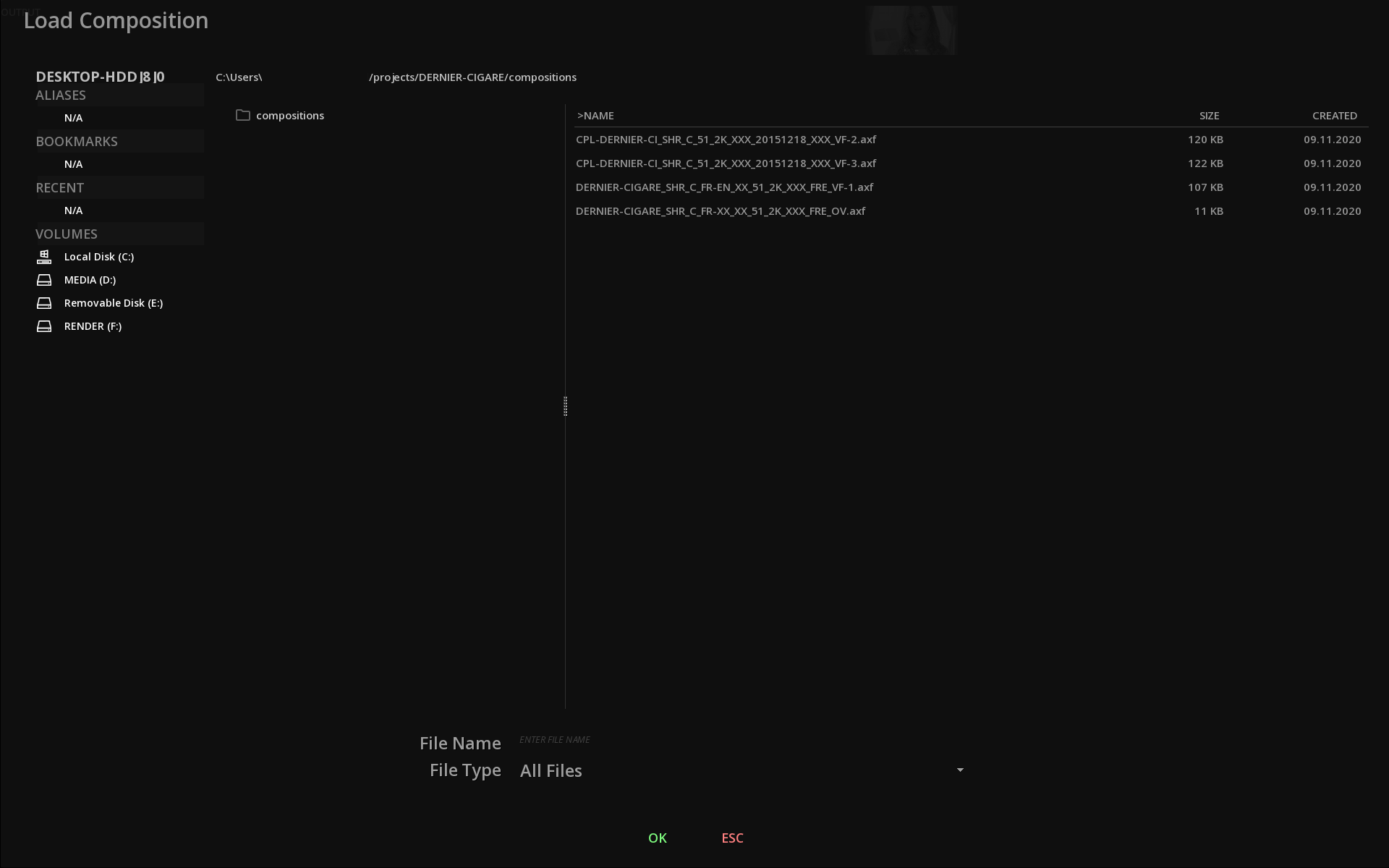
When opening the Load Composition panel, the browser displayed by default the current working disk of the computer.
|
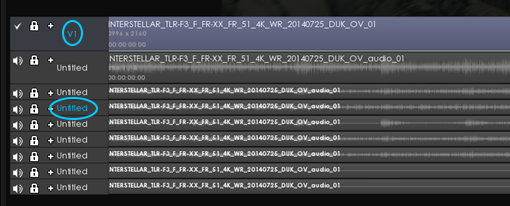
When you load a composition, the clips may appear in red for a short time, the time needed to renew the links. In general, except for a graphical subtitle track (e.g. PNG files), the names of the clips are red when there is no associated media: 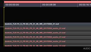
|
6.5.3. Composition Settings
Access the Composition Settings
-
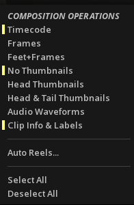
Right click in the Timeline background to display the drop-down menu for Composition Operations and choose Settings:
-
To close the window and get back to the Timeline, click on exit.
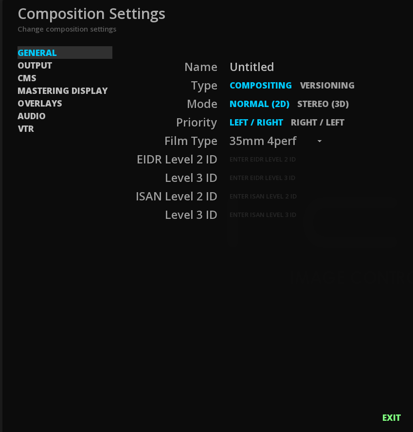
In the Composition settings, you will find different kind of settings, presented in tabs:
| GENERAL |
defines the name, the type and the mode of your composition. |
| OUTPUT |
defines the way the media is outputted |
| CMS |
Color Management System. This parameter sets the composition either in the native color space of the video clips on the timeline, or switch the composition in ACES color space. |
| MASTERING DISPLAY |
define the mastering display based on the SMPTE ST-2086 standard. |
| OVERLAYS |
defines blanking information and image burn-ins |
|
All the parameters of this panel will apply to the current Composition. Loading a new empty TimeLine will restore default project settings. |
General settings
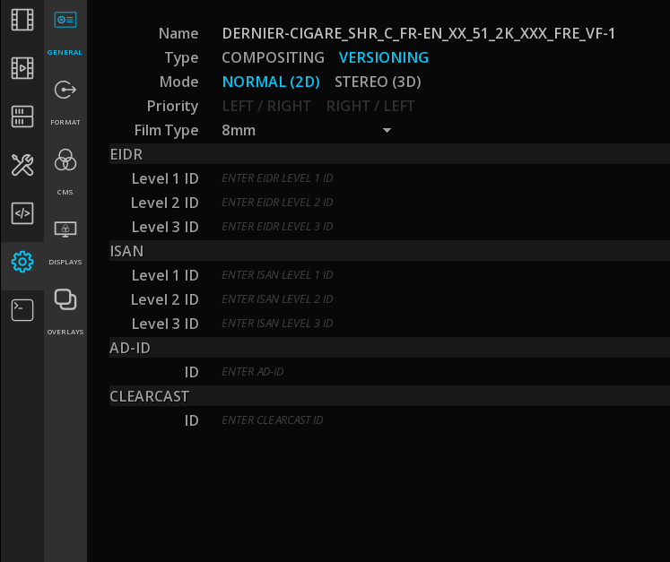
| Name |
Name of the composition. Edit it with a click on the text field. |
| Type |
Choose the type of your composition. "Compositing" is set by default for new projects. |

| Mode |
This parameter set the composition in 3D STEREO or in normal 2D mode. In 3D STEREO mode, you can also chose the priority of the left and right eyes. More information about 3D mode is available in the 3D STEREO guide. |
| Priority |
Enabled when in 3D Stereo mode. |
| Film Type |
Setting a Film type will define how the TimeLine is calculated in Feet+Frames (see section TimeLine in the Player chapter). |
| EIDR and ISAN levels |
Enter EIDR and ISAN identifyers here. The 3 different levels ID are supported. |
| Ad-ID & Clearcast |
Enter Ad-ID identifier and Clearcast number here. |
|
EIDR, ISAN, Ad-ID and Clearcast information entered here will be embedded in the content’s metadata. |
Defining an Output Format
| Preset Output format |
Select the desired output preset in the list based on the dimensions, the frame rates and the pixel aspect. |
|
The video is not automatically scaled to the selected format. In order to fit the picture to the expected output and therefore avoid any undesired crop, use the Pan and Scan function. |
- Custom Output format
-
To define a custom format, select Custom in the Preset drop down menu and enter the desired format, frame rate and pixel aspect:
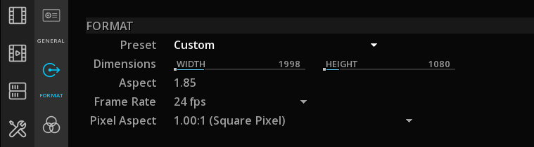
| Dimensions |
Click on the width digits to edit the text and enter the desired value. Press tab to edit the height digits. Finish with enter to save the new dimensions |
| Frame rate |
Choose if the composition will be played from 14 up to 72 frames per second. this setting will affect the playback speed. For more information refer to the TimeCode section of this manual. |
| Pixel Aspect |
Select the desired aspect ratio of the clips size: 4/3, 16/9, or any other ratio from 1 to 2.77. |
|
The internal color processing of the application works in 32-bit floating point. |
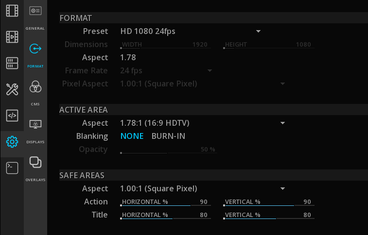
| Active Area Aspect |
select the active image area ratio from the drop down menu thus to exclude letter and pillar boxing from any processing or analysis.
|
| Safe Area Aspect |
select the safe area aspect to display. |
| Safe Action and Title |
define the percentage of tolerance for safe action and safe title in relation with the chosen safe area aspect. Move the slider from one end to the other or type the desired percentage by double-clicking on the existing values.
|
Choosing a CMS

This tab is dedicated to the choice of a Color Management System for your current composition. For more informations, please read carefully the Color Management System chapter.
Selecting Mastering Display
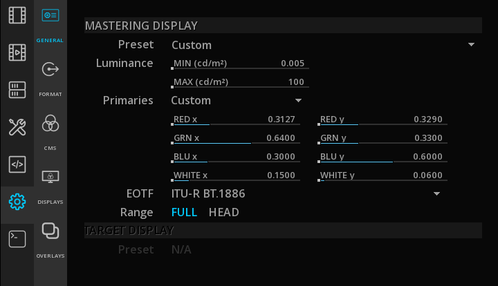
The Mastering display tab allows you to define and to store statics metadata per composition, especially for HDR content.
For more informations, please read carefully the Mastering Display chapter.
Setting image overlays
Overlays are often used when working with dailies and creating proxies for the editing departments.
| Blanking |
Enables image blankings (letterhead and pillar boxing). Blankings are not affected by color or contrast corrections. |
| Opacity |
Allows opacity controls on the blankings |
| Names |
Burn in the image Clip, Reel or File name. |
| Timecodes |
Burn in the image the Source or Record TimeCode. |
| Edgecode |
Burn in the image the EdgeCode. |
| Slate |
Burn in the image the Scene or Take number. |
| Rolls |
Burn in the image the Camera, Lab or Daily number. |
6.6. Clips
In ICE, a clip is the visual representation of any type of asset : video, audio, subtitle or metadata file.
Depending on the assets, like audio tracks for example, the way they are added on the Composition timeline is important.
6.6.1. Adding manually clips to a Composition
Once you have dropped your media in the Media tab of the Command Panel (see Media Tab, you can start adding the clips on the Timeline.
There are several ways to add clips to a composition and they all depend on the context. Some methods will be more appropriate than others in some particular cases.
Sequential Paste
This is the easiest method to manually drop some clips in the timeline.
The clips will be placed in the timeline automatically at the playhead position, one after the other, in the order you have selected them in the Media tab.
-
Select the clip in the Media tab of the Commad Panel (clip turns in grey when selected)
-
Using the mouse, click on the thumbnail then lift it with a quick swipe of the left mouse button. This process is called Lift, Carry & Drop.
The Clip will be attached to the mouse:
To import several clips, select them in the Media tab in the order you want them on the TimeLine using Ctrl + Left mouse button then click on any thumbnail and lift them with a quick swipe of the left mouse button:
-
Once the clip(s) is/are attached to the mouse, press Ctrl+V to drop the clip(s) on the timeline.
The clips will position themselves on the layers, at the playhead position.
|
The Timeline must be configured with the right number of audio tracks prior to the import. This can be configured either from the Project properties, or by adding manually additional layers (press A+ or S+ for example). |
-
Too keep the clip(s) attached to the mouse for pasting them again, choose the option Keep Clips after Drop in the Project Settings / User Interface. When this option is enabled, click Esc to free the mouse.
Stacked Paste
In Stacked Paste mode, the clips will be placed in the timeline in pile, one below each other, starting from the playhead location.
-
Select the clips in the Media tab as mentioned above
-
Once the clip(s) is/are attached to the mouse, press Ctrl+Shift+V to drop the clip(s) on the timeline.
-
Press Esc to free the mouse.
Extended Pasting
When none of the above methods is convenient, extended paste functions are available.
-
With the clip(s) attached to the mouse, press the right mouse button on an empty area of the timeline to display the dropdown menu:
This action opens the Paste Extended tool box:
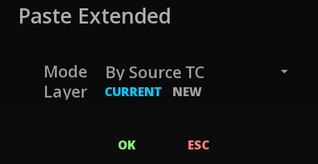
-
Select the desired paste mode with the drop down menu to be applied either on the current layer or on a new one.
The various paste methods include:
| By Source TC |
will place the clips at specific places in the composition, according to their source timecode. |
| By Increasing Source TC |
will place the clips one after each other but sorted by their source timecode. |
| Alphanumeric order |
will drop the clips one after each other sorted by their name in the increasing alphabetical order. |
| Reverse Alphanumeric order |
will drop the clips one after each other sorted by their name in the reverse alphabetical order. |
Clip and composition frame rate
After the import, if your clip appears in red on the TimeLine, it means that your composition settings have not the same frame rate than your clip:
-
To modify them, you can either call the Action menu (press right mouse button from the image Viewport) to access the Composition settings and change them manually, or
-
Press right mouse button on the clip itseld to display the Clip Operations drop down menu :
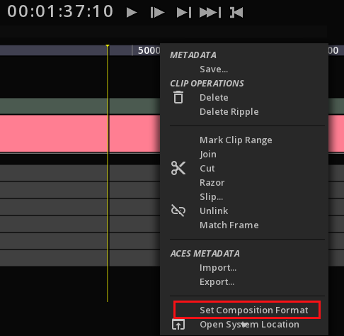
-
Choose Set Composition Format to automatically adapt the composition settings to the clip properties.
6.6.2. Selecting clips
-
To select a clip on the track, click on it using the left mouse button. Clip will change color to light grey.
-
To select several clips, use Ctrl + left mouse button on each of them.
-
To select all the clips, start to select one clip then use Ctrl+A.
-
To deselect clip(s), use Ctrl+D.
-
To select a range of clips, position the mouse on the track next to a clip you would like to enclose and press Shift + left mouse button and drag the mouse over the desired clips. The covered range is bordered in blue.
Alternatively you can use the TimeLine Hot Box to quickly manipulate the clips:
6.6.3. Removing clips
You can remove an entire clip or a range of frames from the composition using several methods :
Delete Ripple
This deleting mode allows to delete a clip without leaving a gap in the Timeline.
-
Select the clip(s), and press Backspace on the keyboard.
Lifting clips or a range of frames
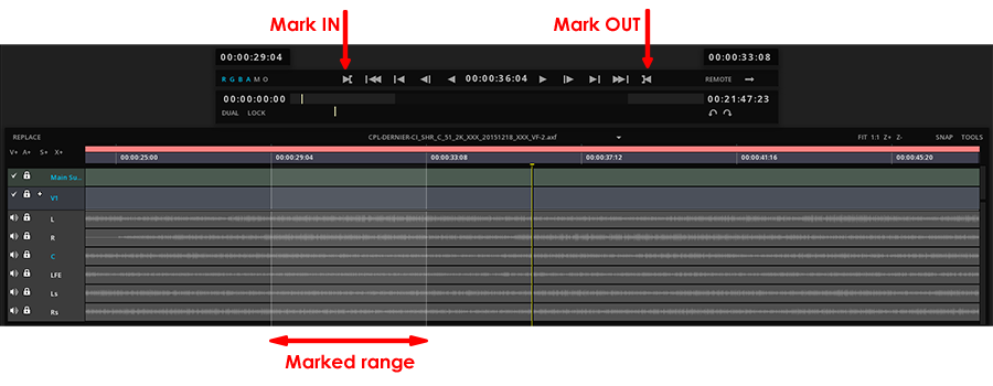
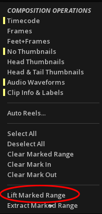
Lifting is the process of removing one or more clips or a range of frames from the composition. The range of the composition to be lifted is defined by the mark in/out range. When lifted, the marked range leaves a gap of the same duration as the mark in/out range.
In order to remove a portion of the composition using the Lift operation, you need first to mark the range using the Mark In/Out tool :
-
to remove a marked region, press Right mouse button on the TimeLine background to display the Composition drop-down menu and select Clear Marked Range or Clear Mark :
-
Alternatively you can use the shortcuts Alt+I and Alt+O to set / remove the marked range.
Once the region is marked, to perform the lift you can:
-
press Ctrl+L
-
display the Composition drop-down menu by cliking Right mouse button on the TimeLine background and select Lift Marked Range.
Timeline after a LIFT operation:
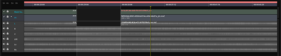
|
This operation occurs on the active layers only. |
Extracting clips or a range of frames
Extracting clips is a process similar to Lift, however there is no gap left by the removed marked range. The remaining clip parts or full clips that were on the right of the mark Out point are moved backwards to the left to fill the gap (also called ripple deletion).
To Extract a clip or a range of frames you must first mark a range and then :
-
press Ctrl+E or
-
display the Composition drop-down menu by cliking Right mouse button on the TimeLine background and select Extract Marked Range.
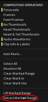
Timeline after an EXTRACT operation:

|
This operation occurs on the active layers only. |
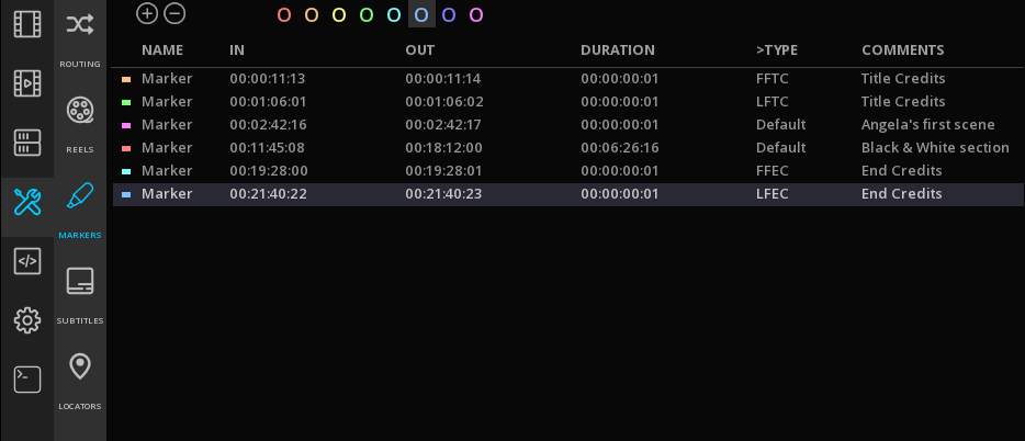
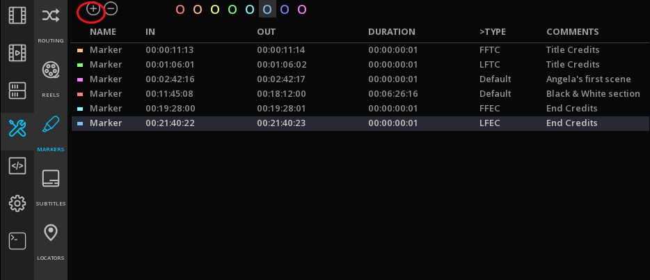
6.7. Markers
Markers define regions of a composition that have a specific meaning.
Typical information located by Markers are for example First frame of Credit, or Commercial break.
-
To access the Markers panel, click on TOOLS in the Command Panel:
6.7.1. Adding markers
-
To Add a Marker, position the Playhead on the desired timecode and in the Markers panel select a color and click +. The Marker is set for a default duration of 1 sec.
-
To mark a range, first define your range and in the Market panel click +.
-
To delete a Marker, select it in the Markers' list and click -.
Markers are represented in the TimeLine by colored triangles and positioned in the Marker’s track:

6.7.2. Navigating through Markers
You can navigate from Markers to Markers with a double click on a time code in the Markers list: the playhead automatically jumps to the chosen frame in the TimeLine.
6.7.3. Defining a markers
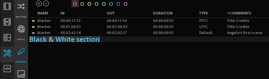
SMPTE markers labels are supported. To add some, select the desired Marker in the list and click on Default on the Type column.
This action display the Markers drop down menu.
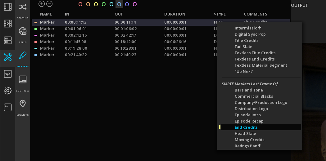
You can also add custom comments.
Select the desired Marker in the list and click on Default on the Comments column and add your custom text:
6.7.4. Exporting / Importing Markers
Save Markers
It is possible to export the markers information in XML.
-
Click on the Export icon on the bottom right of the Markers panel to enter the Save Markers window.
-
Choose a location for your file and enter a name.
-
Finish with OK.

Import Markers
-
To import a Markers file, click on the LOAD icon on the bottom right of the Markers panel.
-
Browse the folder tree on your left, select the file and click OK.
|
Only Markers created using ICE or MIST can be loaded. If you want to import an external file, you can use the Locators. |
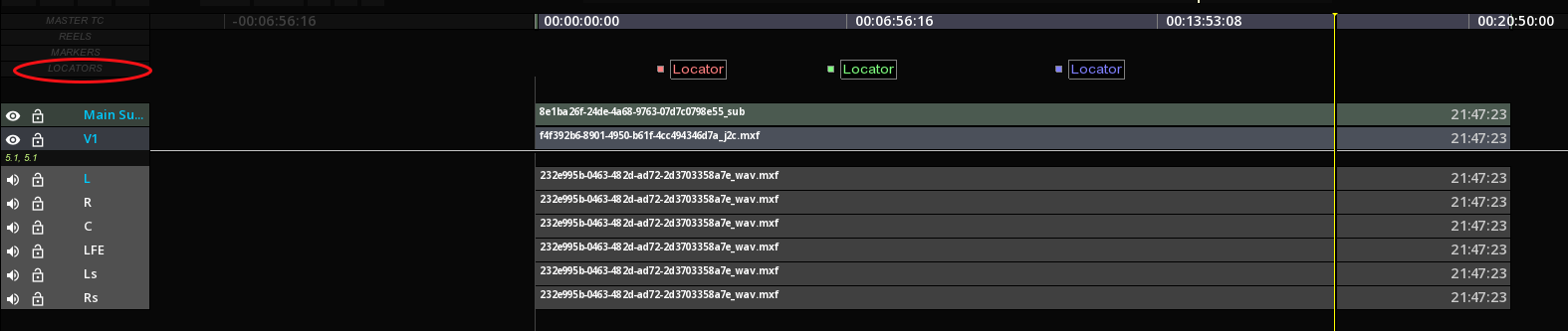
6.8. Locators
If they are similar to the Markers, Locators are only used for custom comments.
-
To access the Locators panel, click TOOLS in the Command Panel:
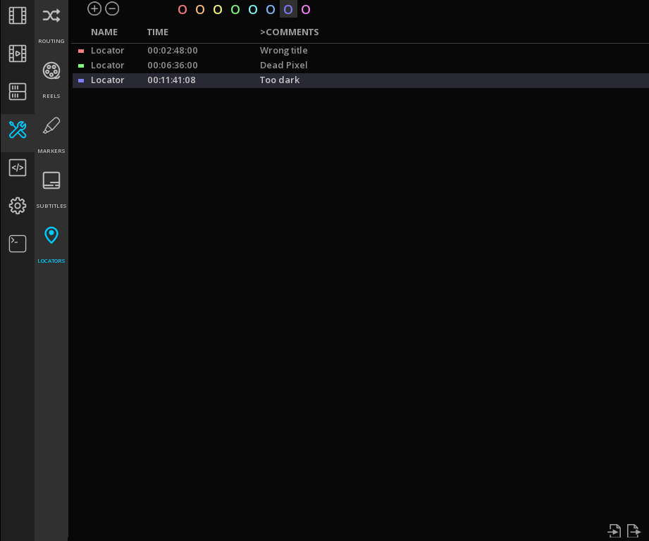
Locators are represented in the TimeLine by colored squares ans positioned on the Locators' track:
6.8.1. Adding Locators
-
To Add a Locator, position the Playhead on the desired timecode and in the Locators panel select a color and click +.
-
To delete a Locator, select it in the Locators' list and click -.
|
You can create several Locators at the same timecode, however on the TimeLine only the last Locator entered will be displayed. |
6.8.2. Navigating through Locators
You can navigate from Locators to Locators with a double click on a time code in the Locators list: the playhead automatically jumps to the chosen frame in the TimeLine.
6.8.3. Defining a Locators
-
Select the desired Locator in the list and click on the empty field in the Comments column and add your custom text.
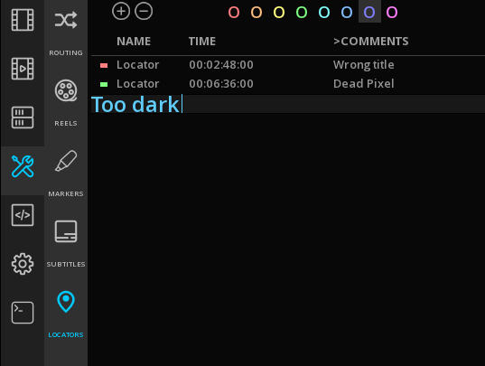
-
To rename a Locator, double click on its name and enter the new text.
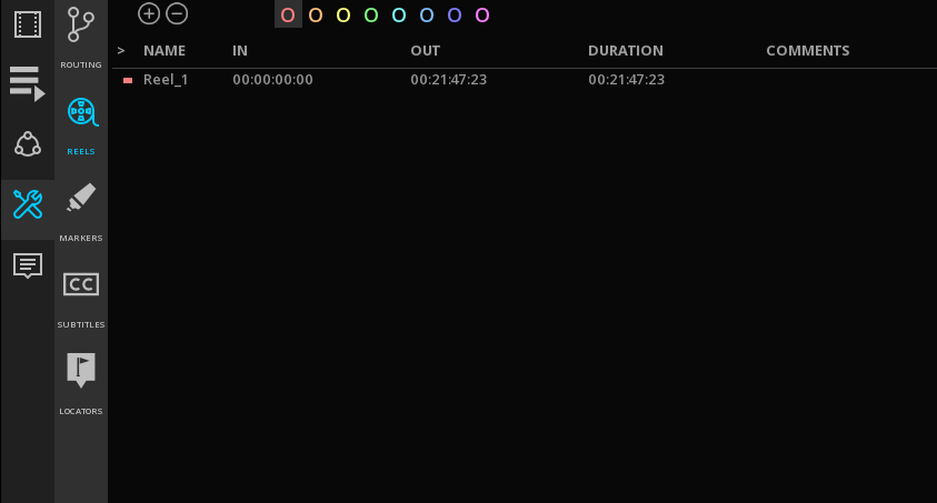
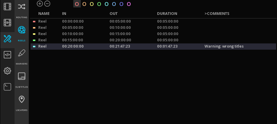
6.9. Reels Management
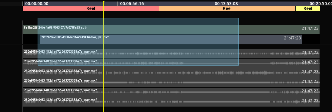
Reels or Segments are often present in DCP or IMF packages.
-
To access the Reels panel, click on the TOOL tab of the Command Panel.
In ICE, the reels or segments are identified by a colored bar on the TimeLine.
6.10. Event Viewer
6.10.1. Overview
One of the major differences between a colorist and an editor is the fact that they have different requirements regarding the display of the shots and how to navigate from one to the other. While the editor will be mostly using the timeline to navigate in the composition, a colorist is more likely to prefer another method. The reason for this is quite simple : when color grading a show, the focus is on the shots as individual pieces of content and their placement in the chronology of the show or the possible transitions between them is not relevant.
A classic editing timeline is far from sufficient to serve the purpose. Instead another navigation tool is preferred. This navigation tool is the Event Viewer (sometimes called the shot viewer).
The Event Viewer also displays the clips available on the timeline in a chronological manner; however, it represents each clip with a preview of one of the frames of the clip. Each preview is displayed next to each other and their dimension is always the same. As a matter of fact, the Event Viewer does not visually represent the length of a clip (or shot). Again this information is of little interest during the color correction process. The diagram below shows you the difference between the timeline and the Event Viewer representations :
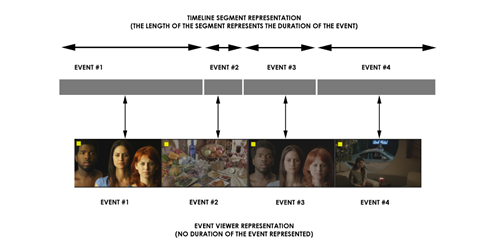
Besides the visual difference, there is also the fact that an Event Viewer allows only a limited number of editing operations. These editing operations are the common ones used by a colorist or an assistant and once again they only serve the purpose of permitting operations needed in this context.
It is also worth noting that the name (i.e. Event Viewer) refers to the objects it displays as “events” and not clips or shots or anything else. From the colorists point of view the timeline is an assemblage of pieces of material that have been spliced together in a chronological manner.
Each of these objects are called “events” because they are actually events occurring at a certain time during the playback of the final show. Once an event is over, it is immediately followed by another event (which can be another piece of material, a transition, or simply a black screen).
A colorist will work on each of these events and make sure that they are all consistent from the color point of view and correspond to the intentions of the director of photography.
In addition to the navigation shortcuts offered by the Event Viewer, there is another important reason to use it. The Event Viewer also gives you access to multiple grading versions per event.
In this chapter, you will learn the following things:
-
How to show and hide the Event Viewer.
-
Understand the information displayed in the Event Viewer.
-
Navigate through events.
-
Insert, delete and replace events.
-
Store and recall various color correction versions per event.
6.10.2. Accessing the Event Viewer
The Event Viewer is a key element during a grading session. As a matter of fact, colorists use it much more than the regular timeline. Therefore it must be accessible at any time by using all the connected input devices, i.e. the mouse or the stylus, the keyboard and of course the control surface.
Using the mouse
If you use the mouse or the stylus, then the Event Viewer can be accessed by clicking on EVENTS located on the lower right side of the screen.
Once you have clicked on EVENTS, its color will change to light blue to indicate that the Event Viewer is being displayed. Clicking once more on EVENTS will cause the Event Viewer to be hidden again.
Using the keyboard
When using the keyboard to show or hide the Event Viewer, you must use the E key shortcut. By pressing E once, you will force the Event Viewer to be displayed. Pressing E again you will force it to be hidden again.
Using the control surface
Accessing the Event Viewer with the control surface is done via a dedicated key. Usually the same key is used to toggle the presence on screen of the viewer. Please refer to documentation for your control surface provided with the software for more information on how to access the Event Viewer.
Once you have used one of the methods above to reveal the event viewer, it will be displayed at the bottom of the screen, like illustrated in the screenshot below:
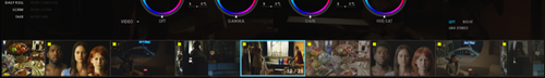
6.10.3. Understanding the Event Viewer
The Event Viewer always displays the events on the currently active layer only. In a multi-layer composition, you must activate the layer you want to work on first. The Event Viewer is immediately updated with the events (clips or holes) existing on the active layer.
The events are arranged chronologically from the left to the right. The leftmost event is the first event on the timeline, while the rightmost is the last event on the timeline.
The current event (the one that you are working on) is always centered in the display. Towards the left you will find the preceding events (or past events), while to the right you will have the upcoming events (or future events).
The diagram below shows multiple events on the currently selected layers and their organization from left to right:
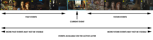
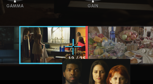
As previously explained, the current event (the one that you are working on) is always centered. To distinguish it from the other surrounding events, it has a light-blue blinking border.
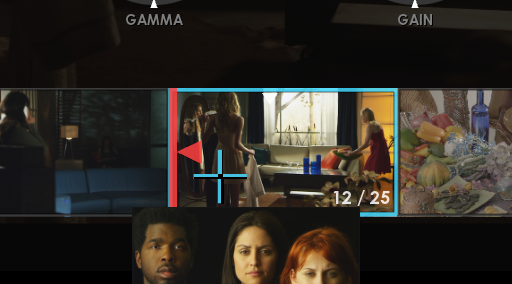
Besides the indication of which event is currently worked on, there are other indications that the current event carries and that are worth looking at. The close-up screenshot below shows the current event centered and exposes some extra information :

The current event also has a display of the current frame number as well as the total number of frames. This indication is updated as you navigate through the event.
Moreover, each event has a “dirty” flag that is displayed on the top-left corner of the thumbnail. This flag indicates that the event has been modified and the modifications have not been confirmed or saved. So, if you don’t save your composition by yourself, the auto-save could do it and then make the flag disappear.
6.10.4. Navigating through shots
One of the top purposes of the Event Viewer is to provide a fast visually-oriented navigation through the shots available in the currently active layer. Rather than locating a segment in a timeline, the Event Viewer allows you to visually locate the event you want to go to by looking at is thumbnail.
The navigation is performed by either using the mouse and stylus, or the same navigation keyboard shortcuts as in the timeline or eventually by using the transport controls of your control surface. In this section, only the specific Event Viewer navigation methods will be explained.
Using the mouse
The navigation to the neighborhood shots (those actually visible) is done via the mouse or stylus. To quickly go to any of the visible shots, you simply need to double-click on its thumbnail.
The playhead will immediately move to the selected event and its first frame will become the current frame. The new event also becomes the current one and it is centered in the Event Viewer. The various information usually displayed on the current event is also updated to reveal the current status.
Select an active track with the Event Viewer
-
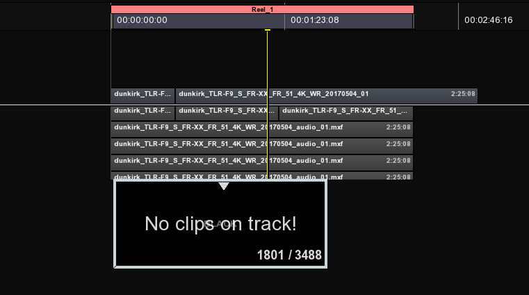
Like the timeline in the editing mode, you can move from a track to an other by using the shortcut Ctrl+Page Up / Ctrl+Page Down. If the track is empty, it will show you only one event with “No clips on track !” written.
Moving through the Event Viewer
-
As we mentioned before, to move through the Event Viewer, you can use the playhead on the timeline like in the editing mode or use the same shortcuts (e.g. press SHIFT + Left to move ten frames before). There is cursor on the top of the current event selected to let you know where you are regarding the duration of the clip.
6.10.5. Inserting shots
During the grading process it could happen that a missing shot needs to be inserted in the timeline. This can happen for various reasons, some being the fact that a VFX shot was missing or you simply need to insert some titles for the purpose of mastering. Whatever the reason, the best way to edit the timeline is still by using the editing tools in the actual timeline or editing mode.
Nevertheless, for some simple operations it is also quite handy to insert shots by placing them between other shots via some quick methods. The event viewer offers the possibility to insert shots before or after a shot, by dropping one or more clips attached to your pointing device.
To insert before or after a shot through the Event Viewer, some conditions need to be met :
-
First of all, one or more clips must be attached to the cursor.
-
Then you must hover around one of the event’s drop zones.
-
Finally you must release the clips by clicking on the drop zone.
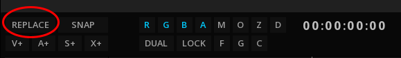
Also you have first to decide if you want to insert or replace by clicking on the button on the top left corner of the timeline to toggle from one to another (or you can press the hotkey INSERT). The one showed will be the one used :
Inserting before the current shot
In the screenshot on the left, the mouse cursor is hovering around the leftmost area of the event. A red bar with a left-oriented arrow head appear to indicate that the clip can be inserted before the one you are on.
Inserting after the current shot
In the screenshot on the left, the situation is similar to the one describe above, but this time the red bar and the arrow head are oriented to the right. This indication means that the clip can be inserted after the one you are on.
Once you have clicked on one of the drop zones described above the clip(s) attached to the cursor will be dropped either right before or right after the event you were hovering around.
6.10.6. Replacing shots
Just as important as being able to insert shots on the fly, without any conforming or editing operations, it often happens that shots simply need to be replaced. There are many ways to replace shots on the timeline and every method has its pros and cons. While the timeline and more editing-oriented and the conforming operations are more adapted to building or adapting full compositions to media changes, they still are somehow complex operations.
A simple method is provided by the Event Viewer, facilitating shot replacement without the need to understand editing or conforming.
To replace one or more shots through the Event Viewer, some conditions need to be met:
-
First of all, one or more clips must be attached to the cursor.
-
Then you must hover around the center of the event for which you need to replace the media.
-
Finally you must release the clips by keeping the Alt key pressed and clicking on the center of the event.
|
If you have multiple clips attached to the cursor, then the next events will have their media replaced as well, starting with the event you started the operation on and continuing with the next events to the right. The operation is fully terminated when all the clips attached to the cursor are released. |
6.10.7. Selecting shots
During the grading process shots must be selected and deselected to perform various operations on them as a group. Shots can be selected any many places with the exact same effect on them, however the event viewer also allows some basic selection operation for the sake of convenience. Below are listed the selection operations that can be performed directly in the Event Viewer.
Selecting and deselecting individual events
The most used type of selection is to select shots individually, one by one. This operation can be accomplished either by using the mouse or the stylus or the control surface.
Using the mouse
To select individual shots with the mouse or the stylus, you need to hold the Ctrl key pressed and click on the event. When doing so, the event gets a light blue shade to indicate that it is selected.
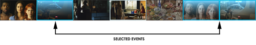
Using the control panel
Individual events can also be selected using the control panel. However, since a control panel does not allow to pick events at random, you position the playhead on the event you want to selected and use the dedicated button on your control panel.
Selecting and deselecting all events
Another very used type of selection is when all events are selected or deselected at once. There is no dedicated method for this in the event viewer, so your only option is to use the keyboard as described below.
Using the keyboard
When using the keyboard, you must press Ctrl+A to select all the events. To deselect all the events, you must press Ctrl+D. Depending on the operation, the events with either get all highlighted with light blue or return to their normal state.
|
When selecting or deselecting all the events, the effect is not limited to the events visible in the event viewer. As a matter of fact, all the events in the timeline will be affected. |
6.11. Playback
6.11.1. Playback Mode
There is several modes for playback available:
|
Play Once |
Play the current composition just once |
|
Play ping pong |
Play backward then forward the composition, endless. |
|
Play Loop |
Play back the current composition, endless |


The “Play once” mode is set by default.
-
To toggle to the other modes, click on the icon until the desired mode is displayed.

6.11.2. Playing Back a Marked Region
To play a specific region of the composition, mark the desired range with IN and/or OUT points:
| IN point | OUT point | Description | Shortkey |
|---|---|---|---|
SET |
SET |
Play forward in the marked region |
Alt+Space |
SET |
SET |
Play backward in the marked region |
Alt+Ctrl+Space |
SET |
None |
Play forward from the IN point to the end of the compositio |
Alt+Space |
SET |
None |
Play backward from the end of the composition to the IN point |
Alt+Ctrl+Space |
none |
SET |
Play forward from the beginning of the composition to the OUT point |
Alt+Space |
none |
SET |
Play backward from the OUT point to the beginning of the composition |
Alt+Ctrl+Space |
|
If the playhead is inside the marked range, the playback starts at the playhead origin |
6.11.3. Playback Information
The timeline’s interface displays some playback information such as:
| FPS |
Current frame rate of the playback in frames per second. |
| Speed |
Define the increment between the frames:
|
7. AUDIO MANAGEMENT
7.1. Immersive Audio
7.1.1. Importing Immersive Audio files
in ICE, the Immersive Audio files are not managed as regular audio tracks.
When importing an immersive audio track into the Media tab, ICE recognizes the metadata and display a different image icon for the file:

The immersive audio files must be placed on an Auxiliary data track on the timeline.
|
if ICE has detected immersive audio metadata in the file, it will prevent the drop of the file on a regular audio track. |
-
Create a new Auxiliary data track by clicking on the X+ button on the left side of the timeline and drop the file on this track.

7.1.2. Dolby Atmos
ICE is supporting Dolby Atmos technology and allows the QC and the playback of the Atmos files.
Supported Formats
ICE supports the following Atmos formats:
-
DAMF (Dolby Atmos Master Format)
-
BWF ADM (Broadcast Wave Format with Audio Definition Model)
-
IAB (Immersive Audio Bitstream) for DCP (including encrypted files) and IMF
These files can be imported in the timeline as stand-alone files or wrapped in an IMF or a DCP package (IAB).
|
When importing a DAMF in stand-alone, select in the directory the file with the extensions .atmos and drop it into ICE: 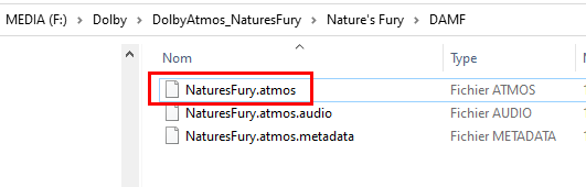
|
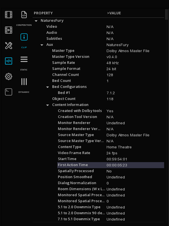
7.2. Audio Analysis
ICE offers a full set of Audio monitoring tools for the quality control. Refers to the chapter Audio Monitoring for details about the different audio scopes.
7.3. Audio Routing
In ICE it is possible to modify the way the audio channels are distributed through the SDI output. This is done using the audio routing matrix:
-
In the Command panel, select TOOLS then ROUTING.
-
To change the channel assignment, select a layer and click on the desired channel.
The Matrix is divided per audio layout for a clear representation of all the audio soundfileds present on the timeline.
8. CONFORMING
Conforming is a step that is sometimes necessary, in many and varied situations: reconnecting an off-line editing, connecting the subtitle tracks or the image sequences to their original files etc. This is also useful in case of media present in the timeline, but which have their source deleted from the project media bin.
The application allows to manage this crucial function with numerous options.
8.1. Conform an AAF and a XML file
Once the AAF or the XML file has been imported using the IMPORT on the menu bar, a timeline appears with red unlinked medias, as shown below :
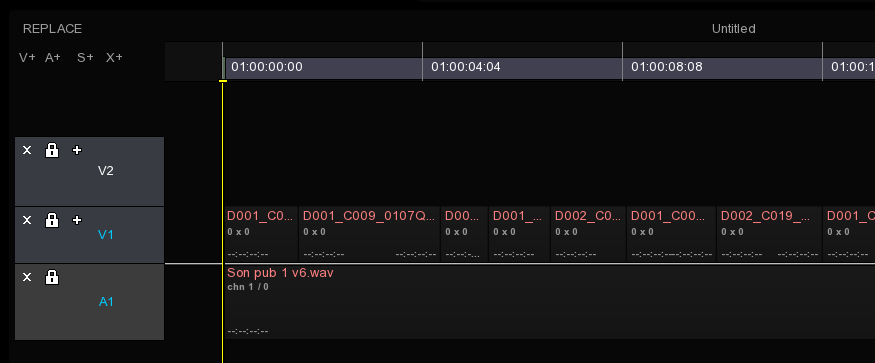
If the media is already present into the project media bin, it will be linked automatically.
|
When importing an XML or an AAF, the tracks could be imported as invisible. Be sure to have the track visible: |
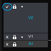
|
When a composition is loaded, by default the Playhead is positionned at TC 00: 00: 00: 00. To go to the first frame of your content, press the "Home" key, to make the playhead positioned at the entry point of the composition. |
You can access to the Conform module by right-clicking on the viewport from the Timeline Module:
Click on CONFORM in the menu bar to access Conforming panel.
In the conforming panel, the media of the composition appear in list form, sorted by type. A series of columns containing media information are adjustable by placing the cursor between two columns :

To move and see the remaining columns on the right of the window, just click on the slider at the bottom of the list and scroll in one direction as in the other :
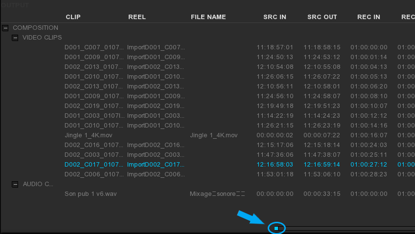
On the bottom of the panel, there is several tools used to configure how the content can be retrieved:
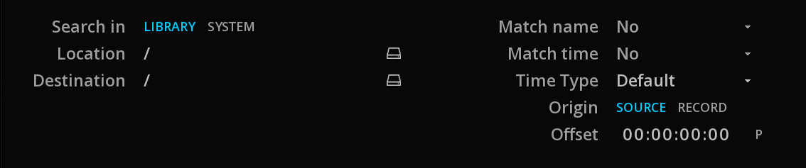
| Search in |
Choose if you want to look for media either in the project media bin (LIBRARY) or in the file system (SYSTEM). |
| Location |
Specifies the navigation path through the media either in the project media bins or system directories. |
| Destination |
Specifies the navigation path through the project media bins, in order to refer the media into the desired folder. |
| Match name |
Searches will be based on the CLIP, REEL or FILE name of the content. |
| Match time |
Searches will be based on the IN, OUT or IN & OUT timecode of the content. |
| Time Type |
Searches will be based on different types of timecode: |
| Origin |
Choose whether the previous timecode’s options are for the TC SOURCE or ORIGIN. |
| Offset |
This option allows to match one timecode with another. For example, in the case of a media whose start time is different from the one of its edit list. |
Sometimes the conforming process requires the media to be renamed or completed in the case of missing information.
It is possible to rename the media by their Clip name, their Reel name or their File name.
-
To rename a clip, first select it in the list.
-
Enter a name and click SET:
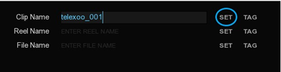
With the TAG tool, the name can be based on an existing parameter. Clicking on it displays a list:
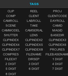
TAGs can be cumulated and added to typed text. For example, if the file name does not have existing information in its column and we want to fill it with information from the clip column, we choose the clip tag and then we type the file extension:
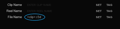
After clicking SET, the media’s FILE NAME column will be renamed:
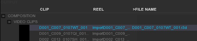
You can apply the renaming function on several clips at the same time: select them using Ctrl and click.
You can also select all the clips Ctrl+A and deselect all of them Ctrl+D.
Once the settings are made, click MATCH at the bottom of the module to start conforming.
After scanning, linked files should display a thumbnail as shown below:
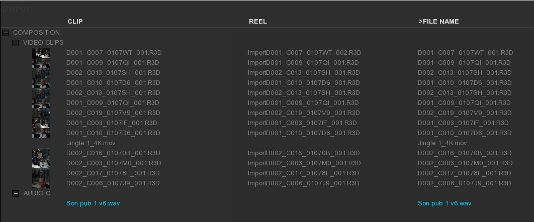
If some files could not be conformed with this first path, the operation can be repeated with any type of search without losing the previous conform.
When all the desired files are linked, just click on ESC to exit the module. Into the project media bin, the conformed medias have been referenced automatically.
8.2. The relink function
In the project media bin, if a media has been moved from the operating system, the media will appear red in the list mode or with a “media offline” information into the thumbnail of the clip.
See Relink Media
8.3. The EDL’s case
The Edit Decision List can be imported using IMPORT on the timeline:
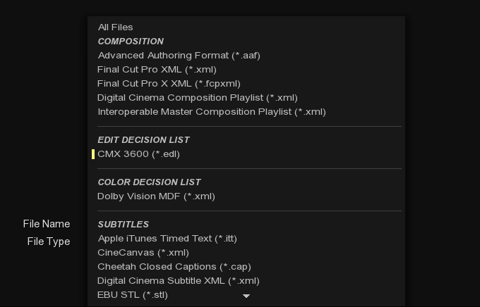
Once the EDL has been chosen, a window will appear in order to select the appropriated settings before importing. All informations about the video and audio tracks, their transition as well as the timecode presents in the EDL will be displayed as a list. A slider on the right allows to go up and down throught the this list:
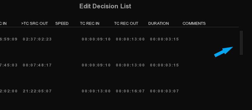
At the bottom left of the window, with the Import As drop-down menu, it is possible to import the EDL as a new layer or a new composition.
In the case of a New layer, for obvious reasons, some settings will be grayed and inaccessible. If a New composition is chosen, the dimensions, pixels and bit depth have to be setup or we can directly select a preset:
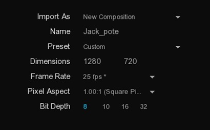
To the right, we can rename the Clip and Reel Name from the EVENT, REEL and COMMENTS columns:
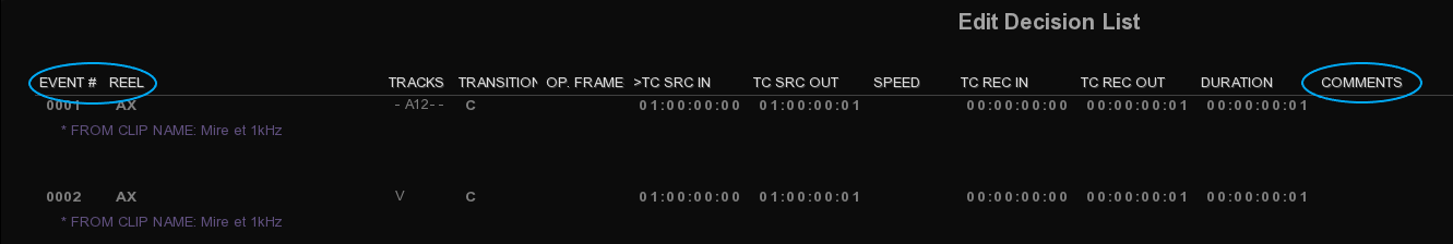
A digit padding setting is available when choosing From Event as well as we can the choice to include or not the extension when using Comment:
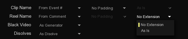
Transition management can be generated by the application or interpreted as being a clip at the discretion of the user. If the EDL contains parameters color transformations, it is possible to keep or ignore them with the ASC CDL drop-down menu.
-
Once all settings are made, click on OK.
9. SUBTITLES & CAPTIONS
ICE is able to import and manage a wide range of subtitles and captions for the broadcast and film industries. To see the full list of formats supported by ICE, please refer to the Appendix Supported Input formats .
In the following section, we will see how to import and inspectsubtitles and captions.
9.1. Import subtitles and captions files
It is possible to import text subtitles and graphic subtitles. A type of track is dedicated to subtitles files on the top of all the video layers in the composition.
9.1.1. Import text profile
The import of standalone subtitle file is similar to a video or a audio assets.
You can import the subtitle file directly from the OS browser by selecting it and dragging it into the Command Panel's Media bin.
9.1.2. Import image profile
The way to import subtitles and captions image profile is identical to text profile.
However, make sure the image files and the subtitle XML file are in the same root folder, permitting to automatically locate the image files to which the XML subtitle file refers.
9.1.3. Place a subtitle file in a composition
To place your subtitles and captions in the timeline create a subtitle track by clicking S+ at the top left of the timeline and place your media like any other asset type or paste it directly to the playhead location.
In case you have selected multiple subtitle tracks, they will be stacked on the top of each other.
|
Like video and audio tracks, you can rename the subtitle track by right clicking on its name to call the LAYER OPERATIONS menu. Then click on Rename and type the desired text (by default, “Untitled”). This will be easier to identify them in the export phase. |
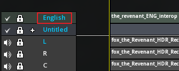
9.1.4. Set the composition format according to the subtitle
It is possible to configure the composition size according to the properties of a subtitle file such as IMSC1. To do this, the file must have the attribute tts: extent defining the resolution of the image in its settings.
Most of the time, this attribute is used in the subtitle files using the image profile and the pixel unit. This is to inform the optimal resolution of the use of the subtitle, so as not to deteriorate its quality which the would make it unusable:
-
From the subtitle track, right-click on the subtitle file.
-
Click on Set composition format.
The composition fits the dimensions of the subtitle file.
In the case of using a subtitle in text profile, the subtitle will use the same resolution as the current composition. The text being vectorial, there is no loss of quality.
9.2. Inspecting subtitles
Once a subtitle has been loaded in the timeline, it is ready for inspection.
9.2.1. Loading font for subtitles
The subtitle file can contain one or more blocks of text, each block itself being able to contain several lines of text. Each block has several properties, including the font face type, size and of course the start and end time during the presentation.
As soon as the subtitle has been placed in the timeline, subtitles are displayed into the Viewport. If not, verify that the associated font has been loaded:
-
Go to the TOOLS panel in the Command Panel. A panel appears to allow you to modify reels, markers, subtitles, locators as well as track.
-
In the SUBTITLES tab, access the FONT tab.
If a font is present in the subtitle, it will automatically appear under the tab FONT.
If the font has been not loaded, no font will be listed and no subtitle will be displayed into the Viewport. Note that a subtitle file can have multiple referenced fonts into the list.
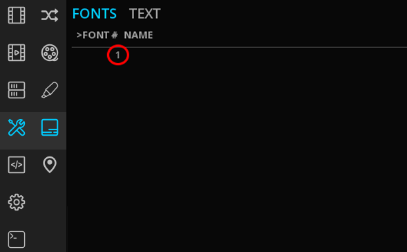
In order for a font associated with a subtitle to be automatically loaded, the font file must be in the same root folder as the subtitle text file. Otherwise, the Arial font is loaded by default.
-
Double-click on the font number to open the Font Library. Fonts present in this list are based on the OS font folder.
-
Select the desired font into the list and click on OK to validate your selection.
|
TrueType fonts ( |
9.2.2. Displaying multiple subtitles
Several active subtitles track can be displayed simultaneously.
Active tracks have their name highlighted in cyan.
If needed you can hide the track by clicking on the check mark to deactivate it and on the X to display it again:
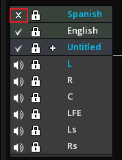
|
In order to check the proper placement of subtitles on the image, you can display a safe-frame guide from the Viewport Hot Box (press alt+ right-click on the viewport). |
9.2.3. Browse subtitles using the spotlist
It is possible to quickly navigate from one subtitle line to another one in the composition.
-
Access the SUBTITLES tab from the TOOLS panel and choose TEXT.
-
Double click on the timecode REC IN or REC OUT :
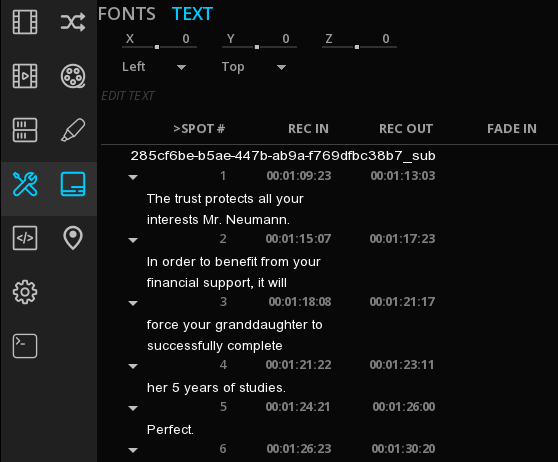
Of course this is based on the timecode of the subtitle track, not on the composition’s one. If your subtitle track is not starting on the first frame of your composition, the timecode will be different.
10. COLOR MANAGEMENT
10.1. Setting the CMS
The Color Management System defines the working color space of the composition. It is possible to mix the color pipelines within the same project, however a composition can only refer to one CMS.
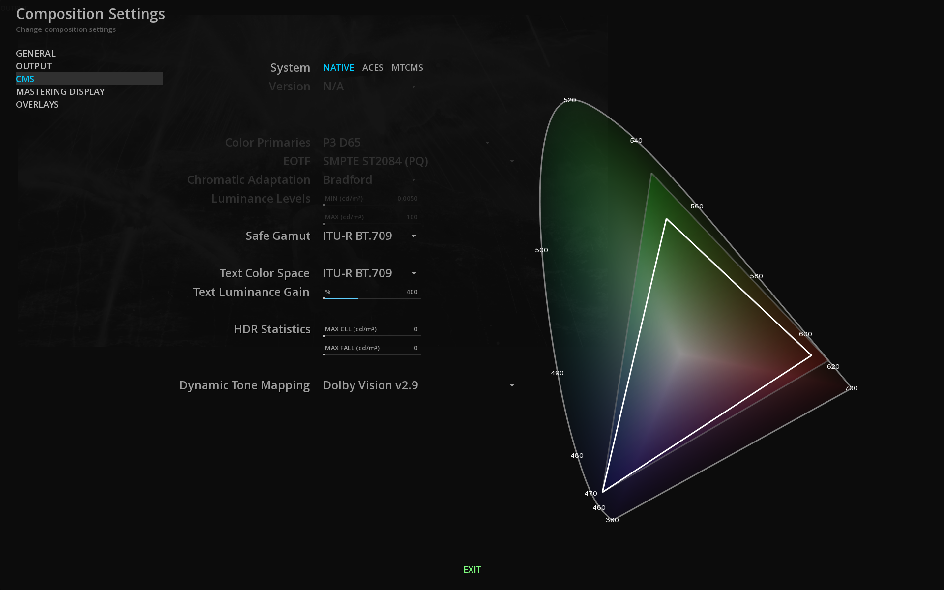
In ICE, color management is done in two steps:
-
define the properties of the source in order to be interpreted appropriately by the color management of ICE, whose internal color processing works in 32-bit floating point.
-
define the target output according to the CMS chosen.
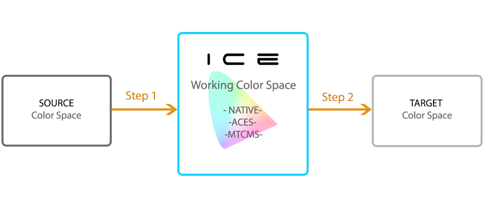
The selection of the Color Management System is done in the Composition Settings.
-
To access the composition settings, refer to Composition Settings.
First, you need to define which color system you want to use for working in your composition.
ICE supports 3 different color management systems :
-
the Native CMS of the content.
-
the ACES color management.
-
MTCMS, the custom color management of ICE.
|
You can quickly switch from one color system to another by calling the Viewport Hotbox by pressing Alt + Right mouse click on the Viewport then go to the CMS tab. 
|
10.2. Native CMS
This system uses the native color space of the source clip and allows you to encode your content without any color conversion (e.g. when using a source already encoded in XYZ for DCP output). ICE manages the media as is.

This means that no processing is applied to the source media unless you decide to simulate a color space conversion or use a LUT.
10.3. ACES
ACES, for Academy Color Encoding System, has been developed by AMPAS (Academy of Motion Picture Arts and Sciences) with the intend to help preserve the color integrity of the content from shooting to archiving.
Specific algorithm allows any kind of source to be processed within the controlled environment of the ACES color space and for a specific output.
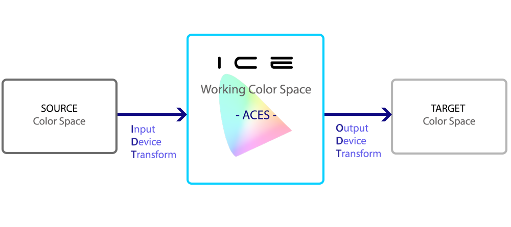
Input Device Transform
When selecting the ACES CMS, ICE will inspect the media metadata to automatically set the right IDT.
However you may want to modify per clip the IDT. ICE has a non exhaustive list of IDTs including the ones defined for cameras and a list of main inverse ODTs.
From the GRADE PANEL in the Source tab, choose the IDT corresponding to the properties of each of your clips.
10.4. MTCMS
The ICE Color Management System is a custom color management system.
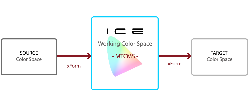
For more precision and reliability, the MTCMS uses current standards to compute on the fly the exact values for every possible color. No interpolation is done like it used to be the case with the LUTs.
If you select MTCMS, then you must select the working color space, the transfer curve and characterize the source via the GRADE panel. By default source parameters are set on Rec709 unless other metadata exists in the media.
MTCMS settings
If you select MTCMS, you must specify the working color space and the transfer curve:
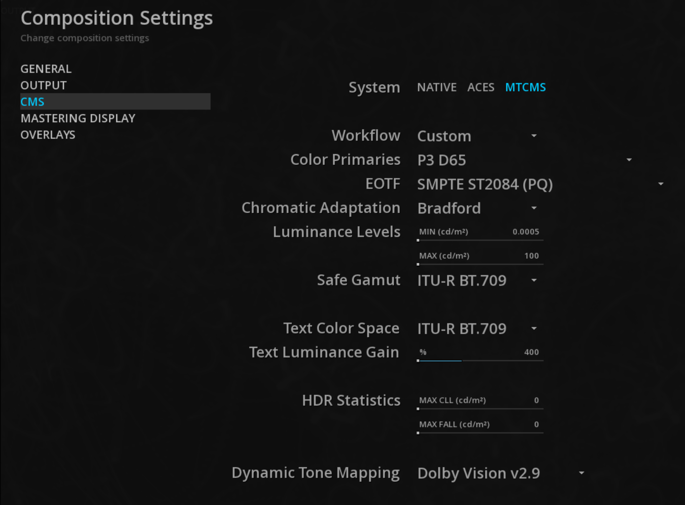
| Color Primaries |
Select the color primaries for your composition from the drop down menu. |
| EOTF |
Select the desired electro-optical transfer function from the drop down menu. The EOTF is also called Transfer Response Curve or gamma curve. |
| Chromatic Adapatation |
ICE supports different chromatic adaptation also called Color Appearance Model (CAM). This adaptation make it possible to match the original RGB color coordinates of the DSM to equivalent CIE XYZ coordinates. These colors are not matching from a colorimetric point of view but rather from a perceptual point of view. This is why ICE offers different methods that will meet the needs of each project. Select a method to apply for adapting the white point of your source media to the one set in the MTCMS:
|
| Luminance Levels |
Define the minimum and the maximum luminance levels of your composition from 48 to 10 000 nits. |
The display of the CIE diagram on the right graphically reflects the settings used. The bright, borderless triangle is relative to your working color space while the white triangle is relative to your Mastering Display settings. Finally the yellow triangle allows you to view a safe gamut.
Safe Gamut :: Select a color space from the drop-down menu to change the safe gamut.
This setting allows you to compare two different gamut.
Text Color Space :: when using subtitles for HDR content, select the original color space of text via the drop-down menu. By defining the text color space, the conversion to a Rec 2020 HDR color space will be performed properly, especially in case of burned-in subtitles.
Text Luminance Gain :: HDR requires the ability to characterize the luminance of subtitles. Indeed, this function is useful when converting SDR to HDR in order to adjust the subtitle signal level or to avoid any violent "overshoot" effect on viewing.
ICE allows to manage their luminance independently of the video track. This setting is effective only in the case of an HDR composition (i.e using an EOTF PQ or HLG) and using the MTCMS system.
By default, a factor of 4 is applied in ICE (e.g. a 100 nits subtitle will appear at 400nits.) It is possible to check the luminance of the subtitles using the waveform scope.
|
When performing an HDR analysis remember that displayed subtitles are taken into account for the analysis. |
- HDR Statistics
-
The MAX CLL and MAX FALL values of the composition are reported here after a global analysis. It is also possible to postpone them manually or to acquire them automatically if these metadata exist in the media (e.g from an IMF).
Refer to the chapter HDR Global Analysis for further informations. - Dynamic Tone Mapping
-
In case of dynamic HDR mastering, use the drop-down menu to select the technology of your choice and thus unlock access to operations specific to them.
10.5. Mastering Display
The Mastering display is used to describe the capabilities of the display used to master the content : CIE (x,y) chromaticity coordinates for RGB primaries, White Point, and min/max luminance of the mastering display.
The characterization of the mastering display based on the SMPTE ST-2086 standard is a key element when working in PQ (ST-2084) and Dolby Vision. These statics metadata are critical for HDR mastering and ICE allows to care these informations through the whole process.
ST-2086 metadata is stored per composition, so in a project with multiple compositions, you can have different metadata settings for the mastering display.
However, ICE does not support only the mastering display metadata in files but also control the display device via their proprietary protocols to send the right metadata and avoid forcing the users to use the monitor menus.
When loading a composition (or changing its settings) ICE will communicate the parameters to the display.
-
Select an existing template monitor:
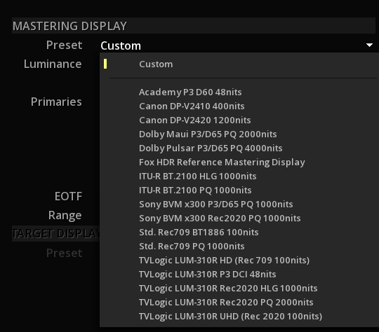
Or custom your setting:
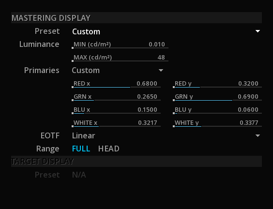
If your monitor is not in the template list, you can create your own mastering display XML by using an existing sample and by editing it. This XML has to be place in
\program files\Marquise Technologies\ICE\resources\displays
|
If the monitor list is empty, it might be a problem of Windows ‘access rights on the folder. In order to fix it, go to the ICE folder, right-click on the displays folder and go to Properties then Security to give the Full control. |
|
Be aware that the list of available monitors will be displayed according to the Dynamic HDR technology selected in the CMS. In the case of using Dolby Vision, the list will be displayed as follows: 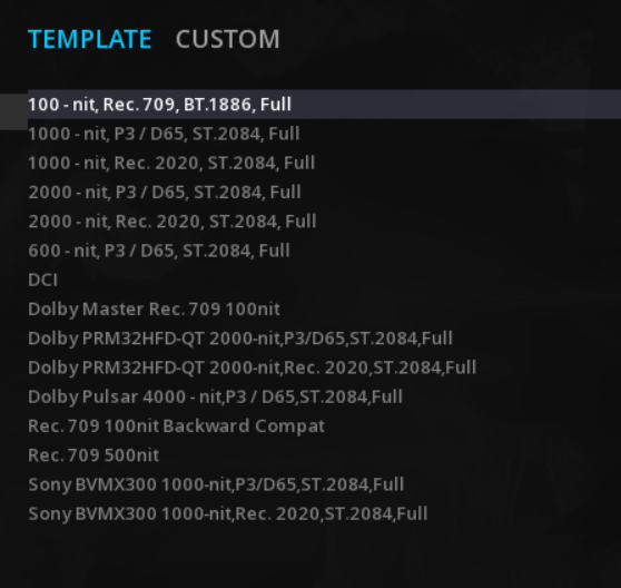
|
|
Do not confuse the Mastering Display of the composition settings for ST-2086 metadata with the Mastering Display parameters in the Projects settings, allowing to configure the communication between ICE and the reference monitor. |
10.6. Source settings
As explained previously in the chapter Setting the CMS, the color management in ICE requires to fill in the colorimetric information concerning the sources placed on the timeline of our composition. With this information, ICE will be able to manage them appropriately for all preview operations (e.g. simulation conversions.). Source settings can be managed individually.
The purpose is to translate its color properties into the working color space.
ICE reviews existing metadata of media. By default, settings are set on Rec709 and BT.1886 but if there is any color metadata present in the file, ICE will automatically load it as Source settings. If not, you need to characterize the source manually.
-
To do this, you must access the GRADE panel (
F9) at the bottom right of the timeline. -
In the Source tab, select the source parameters.
From one colorimetric system to another, the required information may vary slightly.
10.6.1. in NATIVE mode
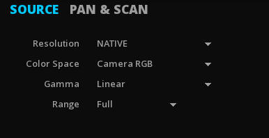
When you are in NATIVE mode, the most important setting you really need to pay attention to, is the Range.
Setup the Range
ICE always compute in FULL range internally meaning that:
-
If HEAD range is selected, ICE will scale the legal range to fill the FULL range.
-
If FULL, range is selected, ICE will keep the native range of the media.
That’s why if no information of range is present in the media, the FULL range will be set by default. This avoid any additional compression if the source is indeed encoded as FULL content but with no metadata saying.
Be careful with this setting or your output may have levels that are not correct.
|
Use the Histogram ( |
Applying a LUT
With the NATIVE mode only, it is possible to apply a Look Up Table per clip.
-
Select the LUT using the drop-down menu on the right:
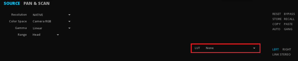
|
You can add your own LUTs in |
\program files\Marquise Technologies\ICE_x.x.x.x\luts
10.6.2. in MTCMS mode
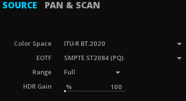
-
If you use the MTCMS system, select the color space, the EOTF and the range corresponding to the nature of your source via the drop-down menu.
-
When converting SDR to HDR content, the HDR Gain is used to raise the levels of an SDR source. The percentage gain corresponds to its equivalence in nits (e.i 100 nits = 100%).
11. ANALYSIS TOOLS
ICE has a full sets of analysis tools, for the image, the audio and also the content bit rate.
It can also load 3rd party QC reports.
11.1. Image Analysis
A large set of Analysis tools are avaialble to perform image quality control.
11.1.1. The Histogram
A histogram is a graphical representation of the tonal distribution in a digital image.
It plots the number of pixels for each tonal value. By looking at the histogram for a specific image one is able to judge the entire tonal distribution at a glance.
-
You can use Shift+H to display the Histogram.
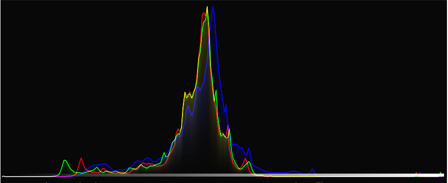
Options
| Style |
The Histogram can be set to display RGB information separately or overlaid (red, green and blue together). |
| Sample |
Show the position in the Histogram of the pixel at the cursor’s location |
| Density |
For film: |
| SMPTE |
Show Video Range (aka Head/Legal). |
| RGB |
Show minimum and maximum values per color channel. |
11.1.2. The Vectorscope
The vectorscope is used to visualize chrominance, which is encoded into the video signal as a subcarrier of specific frequency: it plots the Cb and Cr channels against each other, for the purpose of measuring and testing television signals.
-
You can use Shift+V to display the Vectorscope.
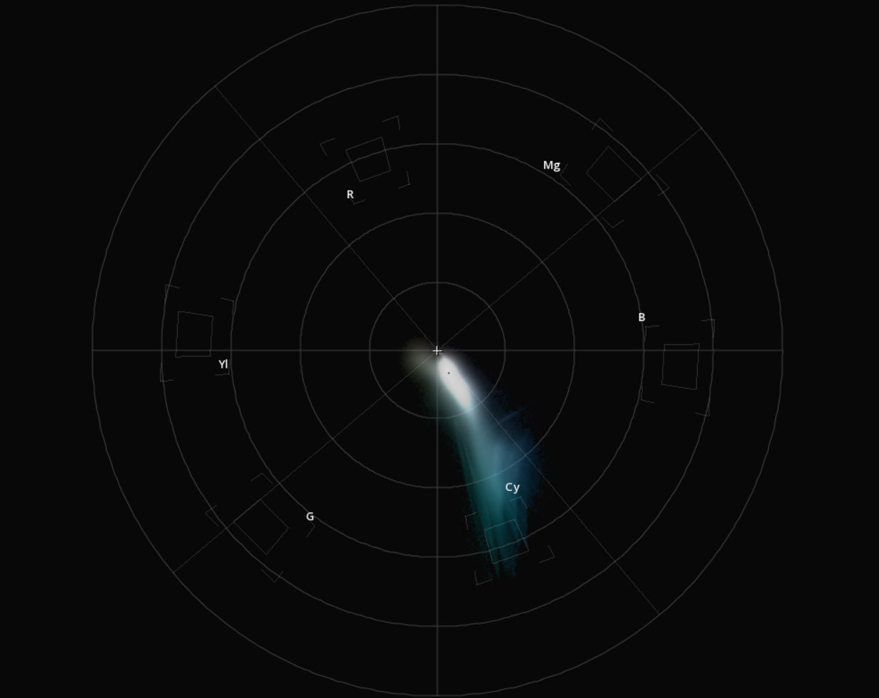
Options
| Labels |
Show/Hide the color labels. |
| Targets |
Show/Hide the color targets. They represent the maximal values according the Matrix chosen. |
| Sample |
Show the position in the Vectorscope of the pixel at the cursor’s location. |
11.1.3. CIE 1931 Chromaticity Diagram
This diagram allows you to see how the signal is displayed within the color space chosen.
You can use Shift+G to display the CIE diagram.
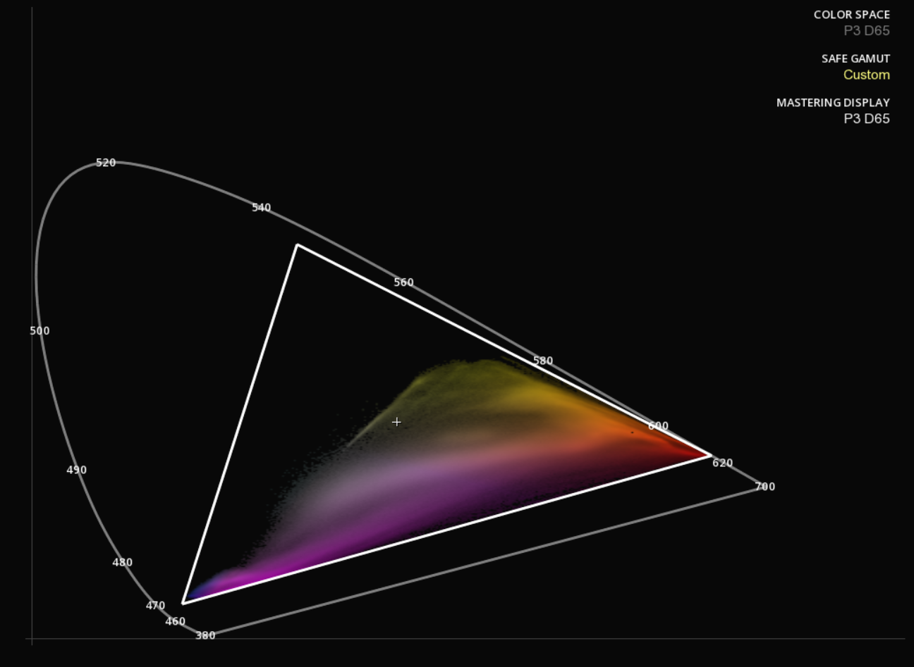
Legend
| Color Space |
Displays the working color space for your content (see Settings | CMS). |
| Safe Gamut |
Display the safe area for a particular color space . (see Settings | CMS) |
| Mastering Display |
Display the capabilities of the Mastering Display . Refer to the Mastering Display section for more information. |
Options
| Sample |
Show the position in the diagram of the pixel at the cursor’s location. |
| Labels |
Show/Hide wavelenghts in nanometers |
| Display |
Show/Hide Mastering Display Information |
| Safe Gamut |
Show/Hide Safe Gamut information |
11.1.4. The Waveform
The Waveform is used to measure and display the level of the brightness, or luminance, of the part of the image being drawn onto a screen at the same point in time.
-
You can use Shift+W to display the Waveform.
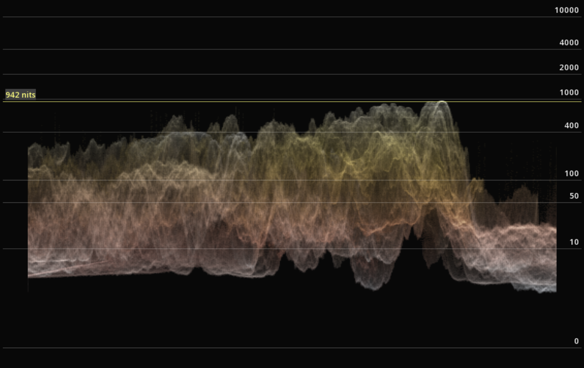
Options
| Type |
You can switch between the traditional video waveform and the ST2084 or HLG modes used for monitoring HDR content. |
| Style |
the Waveform can be set to display information in a large variety of styles. |
| Color Space |
You can choose between the RGB or YCbCr color spaces. |
| Sample |
Move the mouse on the image to show the level at the cursor’s position (yellow line). This value is displayed in percentage in video mode, or in Nits (Candela/sqm) in ST2084 and HLG modes. |
|
When using the type ST2084 the waveform will display the scale in relation to the settings selected for the Mastering Display. |
11.1.5. Zebra patterning
This tools is very similar to the camera zebra mode for controlling the exposure.
The Zebra mode displays in blue the pixels below the boundaries, and in red those above:

-
to display the Zebra, use Alt+Z
|
The Zebra boundaries are defined by the Mastering Display parameters in the Composition Settings. You can also set your own maximal and minimal Luminance values by choosing Custom Mastering display. |
|
The image scopes are affected by the Zebra display, as they analyse the additional red and blue information on the image. |
11.1.6. The Luminance Meter
The Luminance meter is used to measure the photometric brightness of an HDR image. It measures the amount of light that strikes a surface in the picture.
-
You can use Shift+N to display the Luminance meter.

| Max Light Level |
Informs you about the higher light level on the current frame. |
| AVG Light Level |
Informs you about the average light level on the current frame. |
| MaxFALL |
Indicates the highest frame average brightness per frame (entire content). |
| MaxCLL |
Indicates the brightest pixel (entire stream). |
| Sample |
Move the mouse on the image to show the level at the cursor’s position (white line). |
| Live view |
Analyses on the fly the MaxFALL and MaxCLL values of the content while it is playing. You can have different nit scales by selecting the desired one with the drop-down menu. |
| Global view |
Allows you to display the full graph statistics values after the launch of a global analysis. For more details refer to the section HDR. |
11.2. Audio Monitoring
There is a full set of Audio monitoring tools for the quality control.
-
You can use Shift+A to display the Audio meter.
Select a Type of meter and the desired scale for the meter:
-
Click on OPTION to toggle the meters.

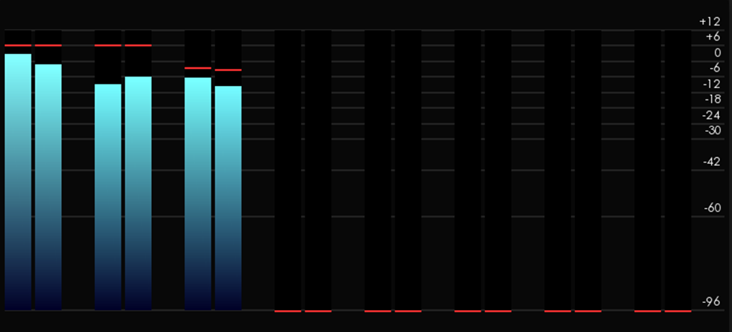

11.2.3. Loudness Meter
The Loudness meter measures the human perceived loudness of an audio content.
Here the Loudness Meter is based on the EBU R128 Loudness recommandation.
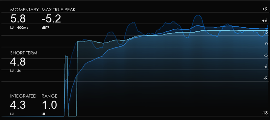
11.2.4. Surround Meter
In this meter, the positions of the full range loudspeakers are marked on a graticule and the amplitude distribution of the sound-field is used to modulate a visual representation, also called "jellyfish display".
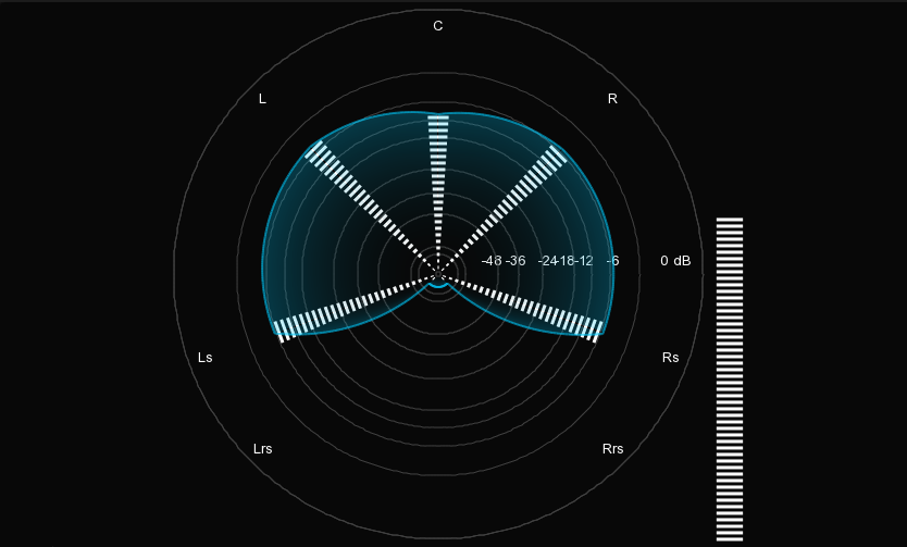
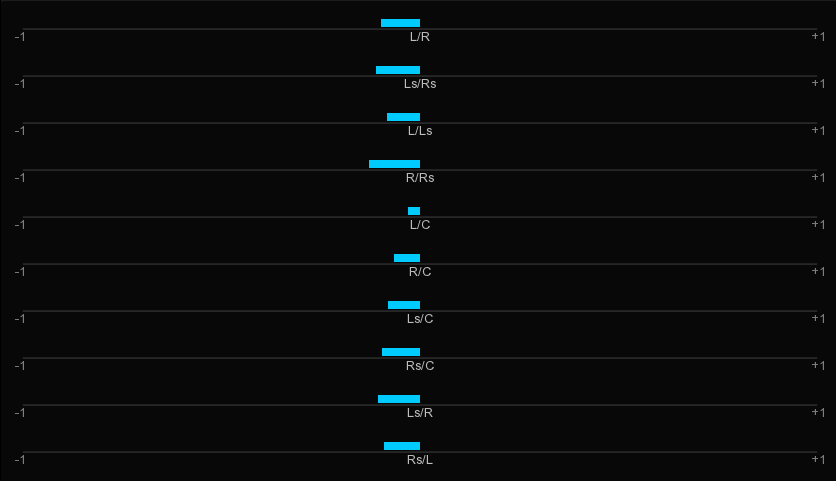
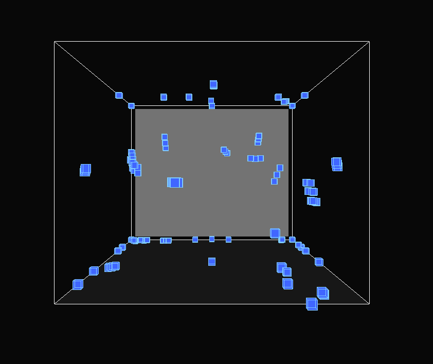
11.3. Peak Signal-to-Noise Ratio
The PSNR computes the peak signal-to-noise ratio, in decibels, between two images. This ratio is often used as a quality measurement between the original and a compressed image. Using the same set of tests images, different image enhancement algorithms can be compared systematically to identify whether a particular algorithm produces better results. The higher the PSNR, the better the quality of the compressed, or reconstructed image.
The PSNR is usually expressed in logarithmic decibel scale. However, you must follow the requirements given by the company asking you a PSNR report. Each company has its own specifications.
11.3.1. Launch a PSNR analysis
-
To launch a PSNR analysis, you need to have the two sources to compare in the Library. The two sources must come from the same content part and have to be of different quality.
-
Open it into the Dual Viewport. For further information, please read the Dual Viewport chapter.
-
Proceed to a Frame Matching and click on LOCK.
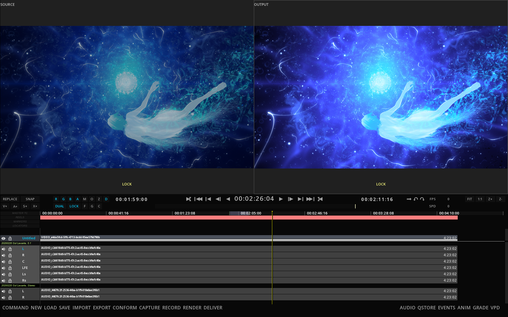
-
Go to the Composition Analysis tool by pressing F6 and select PSNR from the Type drop-down menu.
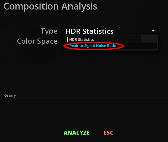
-
Click on ANALYSE to launch the analysis.
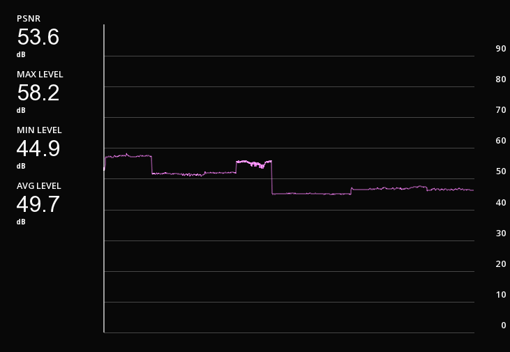
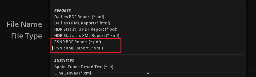
11.4. Bitrate Meter
The Bitrate Meter is used to measure the bitrate of the content playing. For now, it only support IMF and DCP content.
-
You can use Shift+B to display the Audio meter.
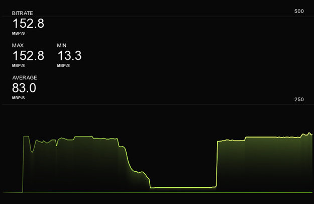
| Bitrate |
Indicates the current bitrate in MBP/s when playing. |
| Max / Min |
Indicates the maximum and minimum bitrate in MPB/s recorded by the meter. |
| Average |
Shows the average analysed bitrate. |
|
the Bitrate meter is active only when you launch the playback. If you stop the playback, the counter will be reset. |
-
You can select the desired scale of reference to read the measures in the drop-down menu.
11.5. Video Pipeline Diagram
The Video Pipeline Diagram allows you to have a quick look at the video pipeline set up.
-
press Alt+F6 to display the diagram:
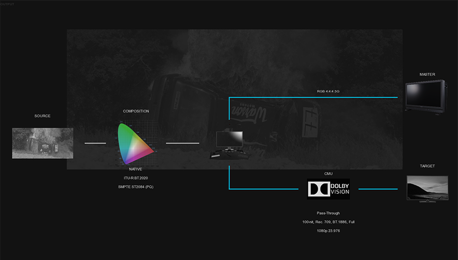
This very useful tool gives you an immediate view of your displays connection settings as well as your color pipeline.
Thanks to a specific color code, you can easyly distinguish the different types of output signals: blue for SDI connexion and cyan for HDMI.
11.6. File based QC Support
Marquise Technologies' solutions integrates with automated file based QC solutions for providing a human review of the error reports.
Currently we provide support for the following automated QC reports:
-
Aurora (Tektronix)
-
Baton (Interra)
-
Pulsar (Venera)
-
Vidchecker (Telestream)
When loading the XML reports from these automated QC solutions, the operator is able to manually inspect the errors flagged for a media by navigating on the timeline from error to error.
11.6.1. Loading a QC report
-
To load a QC report for the content you have on the TimeLine, click on the IMPORT button in the Menu bar of the TimeLine.
-
Browse your directories to select the error report and select in the FILE TYPE drop-down menu the desired QC tool :
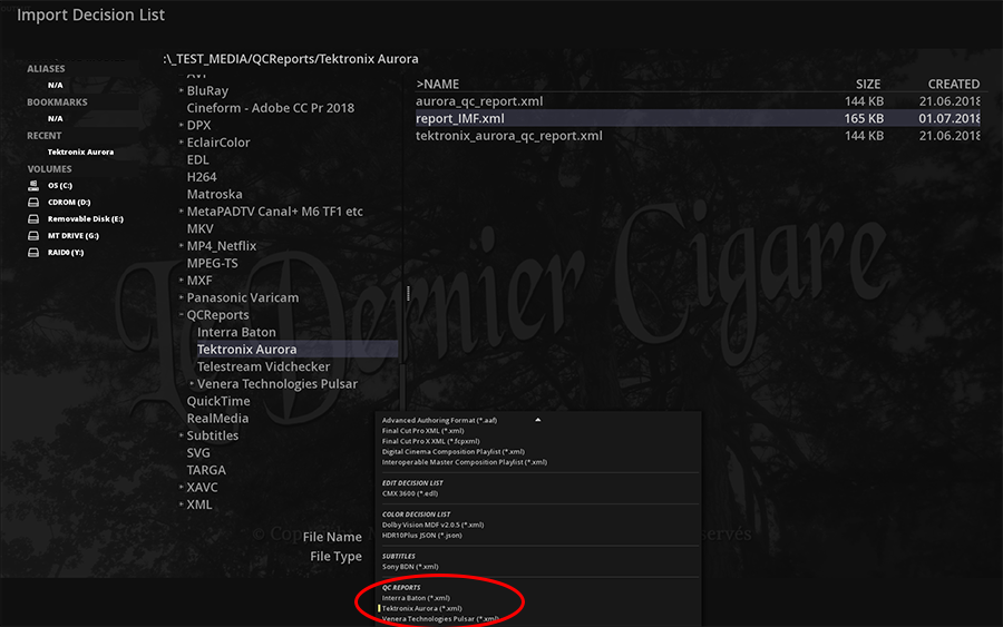
Once the report is loaded, the errors are displayed on the timeline on the Locators' track:
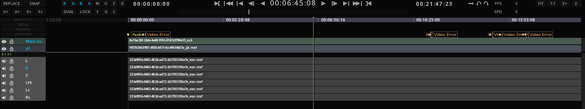
-
To navigate from error to error, open the TOOLS panel from the Command Panel access then go to the LOCATORS tab:
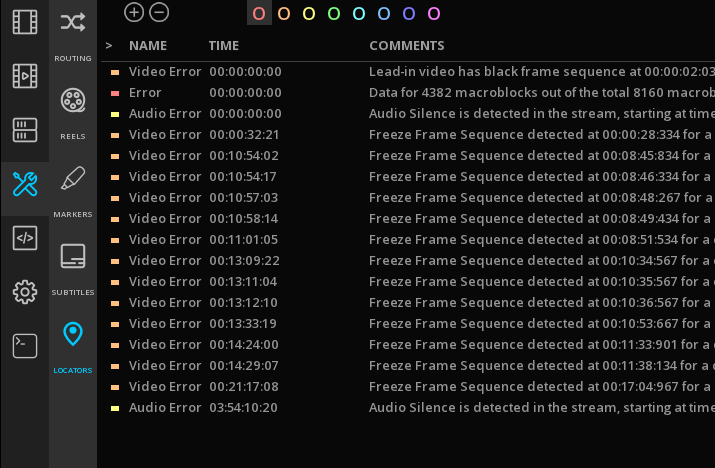
-
Click on a specific Timecode to jump to the location of the error.
-
To display the full error name you can resize horizontally the Command Panel.
12. HDR CONTENT
This chapter describes how to use ICE for HDR content quality control.
12.1. About HDR
12.1.1. What is High Dynamic Range?
“High dynamic range is specified and designed for capturing, processing, and reproducing scene imagery, with increased shadow and highlight detail beyond current SDR video and cinema systems capabilities.” (Society of Motion Picture and Television Engineers® (SMPTE® Study Group Report High-Dynamic-Range (HDR) Imaging Ecosystem)).
HDR offers the ability to capture, process, distribute, and display large contrast ranges, resulting in more realistic images. The images are not just brighter with contrasts artificially dilated.
The brilliances of the objects are more faithful and the details in the high and the low lights are better represented.
HDR makes it possible to have images with more depth and better saturated highlights. Differences in brightness between indoor and outdoor scenes make more sense.
High Dynamic Range moving images capture is a reality since the first high-end digital cameras. RAW images have naturally a very high dynamic range, with an average of 14 stops for the ARRI Alexa and the SONY F65. Those camera manufacturers already offer wide gamut capture, 6K or 8K resolution at up to 120 frames per second. The bottleneck for HDR was the post-production workflows, not ready because not yet standardized, and no capable display devices were available.
Now that some pioneers have lead the way, like Dolby, and that standardization committees and industry alliances have made great works to specify what HDR is, deliveries in HDR have become a reality, pushed by the consumer market opportunities.
-
The Blu-ray association has already published specific metadata and requirements for HDR, based on the HEVC codec like the Ultra HD Blu-ray – HDR disc format using the HEVC, HDR10, and optionally Dolby Vision.
-
The Interoperable Master Format Studio Profile applications have been extended to support HDR content and metadata (also referred as Application 2e+).
12.1.2. Standards
A variety of SMPTE standards specifies the different types of HDR.
SMPTE ST-2084 HDR
ST-2084 is based on the “perceptual quantizer” (PQ) initially proposed by Dolby. It defines the EOTF (for Electro Optical Transfer Function, a Gamma curve) for the HDR10 and the Dolby Vision formats.
This non-linear curve defines how Luminance is increasing above the standard white reference (100 nits), in the spectral highlights. ST-2084 is defined up to 10’000 nits. (Current HDR display devices support a maximum of 4’000 nits – Dolby Pulsar).
SMPTE ST-2086
“Mastering Display Color Volume Metadata Supporting High Luminance and Wide Color Gamut Images”, this standard accompany the ST-2084 and defines the static metadata embedded in the HRD content.
This metadata is used to describe the capabilities of the display used to master the content : CIE (x,y) chromaticity coordinates for RGB primaries, White Point, and min/max luminance of the mastering display.
This is a characterization of the hardware used and has nothing to see with the MaxFALL and MaxCLL metadata, which are statistical measures of the content.
These parameters are essential to know what you are looking at.
SMPTE ST-2094 Dynamic Metadata for Color Volume Transform
The metadata are intended for transforming high dynamic range (HDR) and wide color gamut (WCG) image essence for presentation on a display having a smaller color volume than that of the mastering display. The metadata are content-dependent and can vary scene by scene or image by image.
Four technologies have been currently specified, even though currently the Applications 1 and 4 are more spread.
ST 2094-10 DMCVT – Application #1
A standardization of Dolby’s technology (Parametric Tone Mapping)
ST 2094-20 DMCVT – Application #2
A standardization of Philips’ technology (Parameter-based Color Volume Reconstruction)
ST 2094-30 DMCVT – Application #3
A standardization of Technicolor’s technology (Reference-based Color Volume Remapping)
ST 2094-40 DMCVT – Application #4
A standardization of Samsung’s technology (Scene-based Color Volume Mapping)
HLG
Based on the ITU-R BT.2100, the Hybrid Log Gamma curve is coming from a joint study of both BBC and NHK. Their aim is to insure the backward compatibility with SDR devices and content, a key element for broadcasters in the adoption / transition to HDR. The main difference with ST-2084 is that definition reached 5’000 nits and that is does not carry specific mastering metadata.
12.1.3. Vocabulary
Below you will have an overview of the vocabulary frequently used with the HDR technology used as well in ICE :
-
WCG: Wide Color Gamut - Rec.2020 has 2x more colors than Rec.709.
-
HDR: High Dynamic Range TV (ITU-R BT.2100)
-
SDR: Standard Dynamic Range TV (Rec.601, Rec.709, Rec.2020)
-
HFR : High Frame Rate (100 & 120 fps)
-
HEVC: High-Efficiency Video Codec (H.265) - 2x more efficient than AVC
-
PQ: Perceptual Quantizer Transfer Function for HDR signals (SMPTE ST 2084, ITU-R BT.2100)
-
HLG: Hybrid Log Gamma Transfer Function for HDR signals (ITU-R BT.2100)
-
HDR10: 10-bit HDR using BT.2020, PQ and static metadata
-
DoVi: Dolby Vision – 12-bit HDR, BT.2020, PQ, Dolby Vision dynamic metadata
-
DMCVT: Dynamic Metadata for Color Volume Transforms SMPTE ST 2094
-
EOTF: Electro-Optical Transfer Function.
12.2. HDR Settings
It is important to first check that the composition settings are well set for the content:
-
The HDR statistics
-
The Mastering Display
12.2.1. Setting the HDR statistics
This information is mandatory for any content using PQ EOTF (Dolby Vision, HDR10, HDR10+).
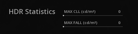
The MAXFALL and MAXCLL metadata may or not may be present in the content, and ICE offers several methods for dealing with the different cases.
Case 1 |
HDR statistics are embedded in the file |
ICE reads the metadata and displays them automatically in the Compositions Settings. |
Case 2 |
HDR statistics are provided in a PDF report |
Report the statistics manually in the Composition Settings. |
Case 3 |
No existing information |
Proceed to a HDR Global Analysis. |
12.2.2. Setting the Mastering Display
The Mastering Display panel allows you to define ST-2086 metadata manually if they are not present in your content. This step is mandatory prior to any HDR analysis.
To get the information about the Mastering display if the metadata are not present in your content, refer to the facility where the content is originated from.
The Mastering Display panel is accessible from the Composition Settings:
-
To access the composition settings, refer to Composition Settings.
ICE offers you a list of preset monitors:
-
select your monitor in the list, and ICE will automatically apply the correct metadata.
|
If the monitor list is empty, it might be a problem of Windows access rights on the folder. In order to fix it, go to the ICE Resources folder: C:\Program Files\Marquise Technologies\ICE\resources Right-click on the displays folder and select Properties: in the Security tab, select the User to modify and add Full Control capabilities. |
If your monitor is not listed, you can define custom settings by adding manually the necessary information to caracheterize the mastering display:
To add your monitor in the list, copy and modify a XML file from the displays folder, and add it back in the same folder:
C:\ProgramFiles\Marquise Technologies\ICE\resources\displays
12.3. HDR Tools
This sections details the different tools ICE offers for HDR content QC.
12.3.1. HDR Global Analysis
The HDR global analysis tool measures the light level of the composition range defined by the user to obtain the MaxFALL and the MaxCLL values.
Setting the Active Image Area
Before the launch of the analysis, you need to define the aspect ratio of the content to exclude any blanking area from the analysis which could affects the results:
-
In the Composition Settings, chose Overlays and select your frame aspect ratio.
|
To verify your settings display the Active Area guide using Alt+B |
Starting the Global Analysis
-
Use F6 from the TimeLine to open the Composition Analysis panel:

-
Select the Source Color Space corresponding to the content and launch the analysis by clicking on the Analyze button.
Display analysis results
Once the analysis is completed, you can access the results using the Luminance Meter:
-
Call the Luminance Meter using shift+N.
-
Choose Global in the options menu to display the full graph of the analysis:
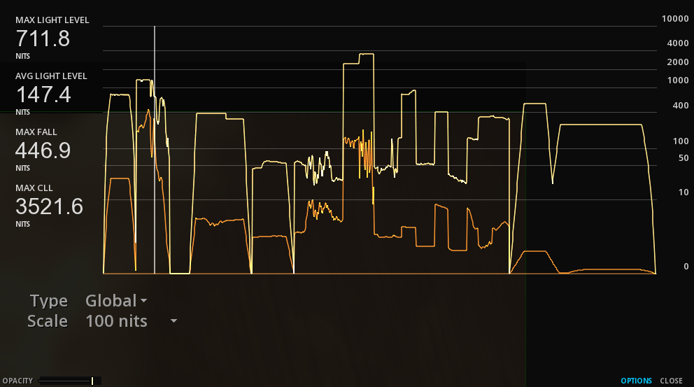
The first values displayed at the top left are the MaxFALL and MaxCLL values of the current image displayed on the viewport. The values below concern all the analyzed content.
The HDR statistics values are reported automatically after an analysis into the Composition Settings in the CMS tab.
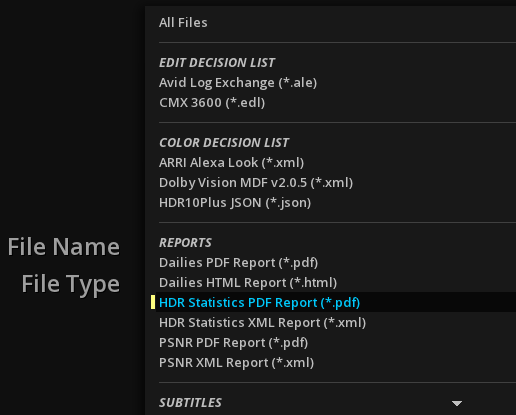
12.3.2. DMCVT Metadata Inspector
If the HDR content has DMCVT information, this dedicated Metadata inspector allows you to read them, whether they are embedded in the file or on a separated XML file.
-
To display the DMCVT Metadata Inspector use Shift+D
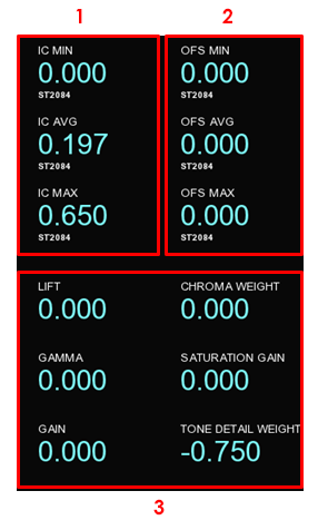
1 |
shows the minimal, average and maximal values expressed in ST2084 PQ. These are the Image Characteristics values. |
2 |
shows the offset for minimal, average and maximal values. |
3 |
color-grading values of the HDR trim pass (i.e. lift, gamma, gain, chroma. saturation and tone detail). |
12.4. Dolby Vision QC
Dolby Vision is an HDR technology developed by Dolby Labs using the PQ curve on the operating principle of Parametric Tone Mapping.
12.4.1. Dolby Vision Content Mapping versions
ICE supports the three versions of Dolby Vision’s algorithms: the Dolby Vision Content Mapping version 2.9 (CMv2.9), and the Dolby Vision Content Mapping version 4.0 (CMv4) and 5.0 (CMv5).
-
To select your desired version of the Content Mapping, go the Composition Settings, CMS tab.
12.4.2. Content Mapping Unit (CMU)
The Dolby Vision Content Mapping Unit (CMU) is able to emulate a number of secondary display targets and aims to produce images adapted to those displays. It maps the content with the metadata for a specific display, could it be at a standard brightness (e.g. SDR 100 nits) or higher. The CMU is therefore essential for the creation of Dolby Vision metadata content, otherwise it is impossible to monitor. However, keep in mind that there is no picture encoding process done by the CMU.
The Dolby Vision PQ images as well as the color volume transform metadata are sent to the CMU which "renders" the images before they are outputted to a connected display device.
ICE supports the eCMU (external CMU), as well as the iCMU (internal CMU). Both requires a valid Dolby Vision license.
|
If you need to preview/QC the color processing of a Dolby Vision content, then a iCMU license or a eCMU is necessary. Inspecting the metadata only does not require Dolby’s CMU. |
Setup of the eCMU
ICE outputs the Dolby Vision metadata over the SDI to the eCMU (also known as tunneling). An Ethernet connection allows ICE to control the eCMU.
The eCMU has to be setup following Dolby Vision CMU user’s manual. The following picture shows a typical case to setup properly the displays:
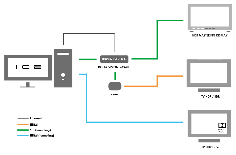
To allow ICE to control the eCMU, select eCMU in the Project Settings, Dolby tab.
The good communication between ICE computer and the eCMU can be verified on the eCMU Home Page by typing its IP address into a web browser:
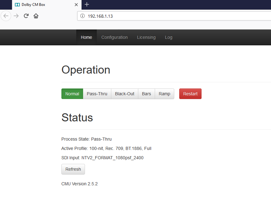
|
Sometimes the Firewall can interfere with the connection between the eCMU and ICE computer. Remember to configure it accordingly. |
|
The eCMU’s status is available into ICE thanks to the Video Pipeline Diagram by pressing Alt+F6. |
Go to the eCMU Home Page to control the eCMU:
-
To perform color corrections, the signal must be set on Normal.
-
If Pass through is selected, the image is displayed without the corrections (bypass).
Setup of the Video Output with the eCMU
In order to display the Dolby Vision technology in an appropriate way, the video output settings into the Project Settings (F1) have to respect some rules:
| Format |
The RGB 4444 format is mandatory |
| Transport |
Choose the SDI level B. |
| Scaling |
Scaling must be setup on HEAD |
| Pixel Format |
Dolby Vision requires a minimum precision of 12 bit. In ICE, select 16 bit. |
Setup of the iCMU
-
To opt for the internal CMU, in the Project Settings / Dolby / Dolby Vision tab select iCMU.
When using the iCMU, the image output is already "rendered" before it is sent through the SDI.

About HDMI Tunneling
This features refers to the capability of ICE to output the Dolby Vision metadata through HDMI using a AJA Kona5 or a AJA Corvid 88, directly to a Dolby Vision consumer TV device to simulate the behavior of the image.
However, for a proper QC, we recommend to use the iCMU or the eCMU.
12.4.3. Composition settings
The Composition settings need to be carefully chosen for the QC of Dolby Vision content.
Setup the color pipeline for Dolby Vision
This chapter will only explain how to setup the CMS for Dolby Vision content.
If you need further information on Color Management in ICE, please read the chapter Color Management.
-
To setup the Color pipeline, go to the Composition Settings by right-clicking on the viewport then go to CMS tab and choose a color system.
| NATIVE |
Choosing the NATIVE mode in ICE for Dolby Vision content management requires a source in PQ rec2020 or P3. Also, be sure that no Look Up Table has been applied on it. |
12.4.4. Inspecting Dolby Vision metadata
ICE allows to control the Dolby Vision metadata through the use of the DMCVT Metadata Inspector (please read the section HDR Tools for additional explanations.)
The color used to display the values of the metadata in the DMCVT Metadata Inspector is related to the origin of the metadata:
| Blue |
the metadata can be edited in live. |
| Yellow |
the metadata is editable but the live mode is not active. |
| White |
the media is read-only. |
|
If the CMU is connected, the values will always be displayed in blue: |
The presence of metadata into the timeline is shown as a color bar on each clip with metadata:

If there is no bar (and the dynamic tone mapping is well selected), it means that your content has no metadata or that the values have been reset.
The color of the bar is identical to the DMCVT Metadata Inspector colors.
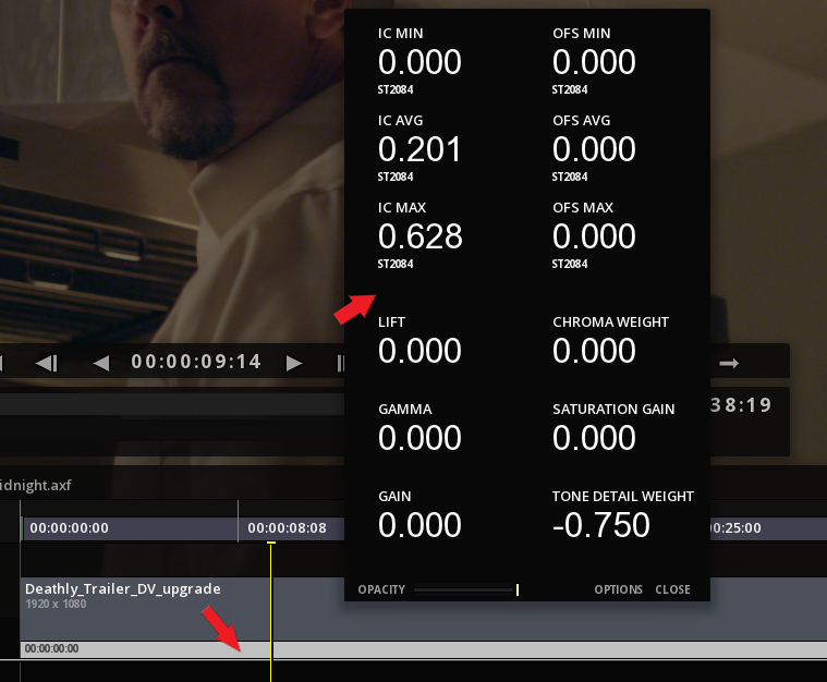
In a case of overlapped tracks, ICE will always display the values of the top track into the DMCVT metadata tool but also when exporting the metadata.
If you want to be able to read the lower track metadata, you can hide the top track by clicking to the left of the padlock:
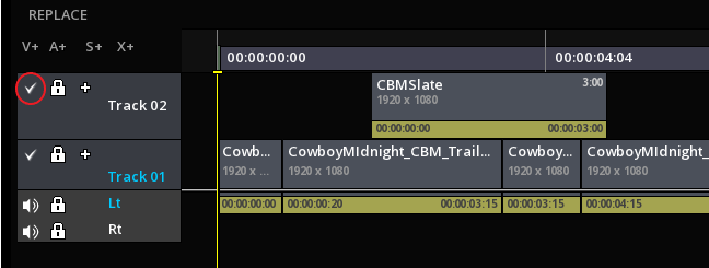
13. DCP QC
ICE offers special tools for a proper QC and validation process of DCP packages.
ICE is able to work with complex packages, including multi CPLs and multi PKLs content as well as supplemental packages.
ICE support INTEROP and SMPTE DCPs.
13.1. Importing a DCP
Importing a DCP into a Project is similar to the process of ingesting a DCP into a DCI compliant server. Each DCP has at least one composition playlist (CPL) for the original version and possibly a number of sub versions, each with its own CPL.
There is different ways to import a DCP package:
-
Drag the DCP (root folder) directly into the Timeline of an existing project.
-
Use the Import function from the starting menu.
-
Create a new project using the DCP Import tool.
Once the DCP is imported within a project, all the elements in the timeline are ready for screening, quality control, etc.
13.1.1. Drag & Drop a DCP
Refer to chapter Media Import Drag & Drop
13.1.2. Import a DCP with the IMPORT function
Refer to chapter Media Import Import Function
13.1.3. Using the DCP Import Tool from the starting menu
The DCP Import tool automatically creates a Project and places the video, and audio essences of the DCP CPL into a composition with each clip arranged in the timeline just as it is referenced by the DCP CPL.
-
Click on DCP Import from the Radial Menu:
If the DCP has sub versions then their additional essences (if any) are imported to the same chosen media folder as the original DCP’s essences. Each sub version’s CPL is used to create a new Composition within the Project.
This way the operator may import a multiple version DCP in a single process and easily switch between the different Compositions.
Package Directory
-
Select the DCP to import using the browse button:
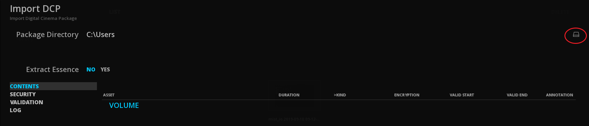
Once you have selected the package folder, and pressed OK, the contents get quickly analyzed and the various elements are then displayed in the exploded directory tree-view. You may scroll through the directory tree and expand or collapse individual elements by clicking on the plus and minus signs to the left of each item:

|
Do not modify the folder’s name or contents in any way or you risk destroying the DCP. |
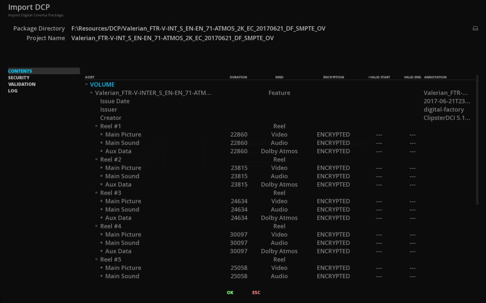
In the screenshot above, the various composition playlists are displayed. Each of them contains one or more reels. These reels also contain a video track and optionally audio tracks and subtitles.
The name of each asset is displayed in the left most column while additional metadata is displayed in the remaining columns as available or relative to the asset itself. This may help to quickly identify the contents of a particular DCP and its sub versions before going through the actual process of importing it, especially if the DCP name does not provide the information you need to do so. This may be the case with sub versions or with multi-reel DCPs.
Project Name
This is where you chose a name for your Project that will contain the entire contents of the DCP you wish to import. By default the folder’s name of the DCP will be displayed.

-
To modify the name of the Project, click on the Name text field, enter a new name and press Enter or click outside of the Name text field.
13.2. DCP Validation
Using the DCP Import Tool from the starting menu, it is possible to validate the content of your package.
13.2.1. Contents tab
The Contents window displays what is present in the DCP: resources and metadata are clearly displayed for an immediate overview of the package. We can at a glance know how many CPLs are in the package with how many reels and for each of them, see the presence of video assets, audio and even auxiliary tracks (e.g. Dolby ATMOS). The ENCRYPTION column also allows us to know immediately if the content has been secured with a KDM.

Click on the + and - of each category to extend the view of the tree or reduce it.
13.2.2. Security tab
This tab can be ignored if the DCP is not encrypted. This is where the DCP Key Delivery Message (KDM) are to be loaded BEFORE the DCP is imported.
Make sure that the KDM for the CPL our are imported has been made using the software’s certificate.
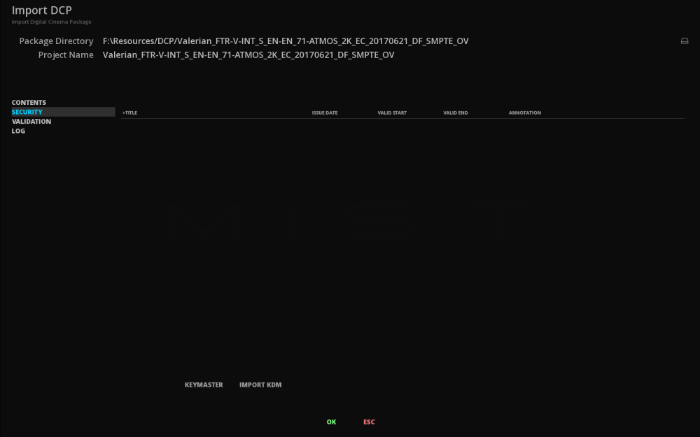
There are two ways to import a KDM:
-
By loading it from the Marquise Technologies platform called "KeyMaster":
If you have a KeyMaster account and the KDM is avaialble on the platform, it will be downloaded directly when clicking the KEYMASTER button.
-
By importing a KDM from the System:
When you import a secure DCP, the DKDM folder is scanned to find the KDM referenced by the Secure DCP itself to decrypt its RSA and AES keys as well as the subsequently AES encrypted essences.
The following address shows where the DKDM folder is located in your system:
C:\Users\your_login_name_here\AppData\Roaming\MarquiseTechnologies\dkdm
As long as the unaltered KDM is placed in this folder the content will automatically parsed to determine the proper KDM for each DCP CPL it needs to decrypt.
|
You may store as many KDMs in the DKDM folder as you like but it is a good idea to store the originals in another location and purge the DKDM folder periodically for the sake of organization. |
-
To import the KDM click on the Import KDM button then in the new opened window, navigate to find your KDM file through the system. The loaded key appears in the KDM list:
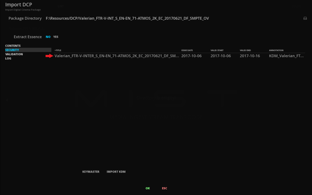
If the KDM is not correct and therefore can’t decrypt the content, it will be loaded in the timeline but the file will appear as corrupted (i.e. noisy pictures etc).
Even if you can not access the content as it is read in case of a faulty key, you will still be able to import the package to check its structure.
13.2.3. Validation tab
When importing a DCP, it is possible to launch a Validation in order to check the integrity of the package. Test are based on standards used by DCI specifications.
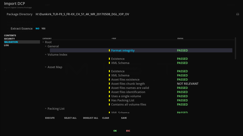
-
To run a validation test, click on EXECUTE. The package is analyzed in its entirety and depending on its size, the time required to analyze one DCP from another may vary.
The SELECT ALL and DESELECT ALL buttons allow you to select and deselect the tests in the list. The CLEAR button is used to erase the last status of past tests.
As soon as the validation test is finished you have the possibility to export a detailed analysis as a PDF report. To do this, click SAVE and set the destination path for this report. The purpose of each test is detailed in the report in order to be able to rectify a possible error in case of failed test.
The report has several types of status:
| PASSED |
Displayed in green. The test in question was successfully completed. |
| FAILED |
Displayed in red. The test has failed. |
| WARNING |
Displayed in yellow. Unlike the FAILED, this test result will not prevent the operation of the DCP. Nevertheless, it draws your attention to some results. |
| NOT RELEVANT |
Displayed in white. The test is not relevant to the package. It can not succeed or fail. (e.g. Key delivery test category for a non encrypted DCP). |
| N/A |
Test has not been performed yet. |
An explanation of the validation tests can be found in the Appendix DCP Validation.
13.2.4. Log tab
If a DCP package is corrupted and cannot be opened, the Log window will open showing the details the errors found in the package.
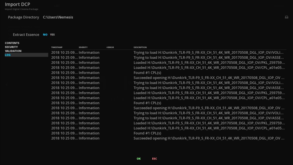
13.2.5. Confirm the import
If you don’t need to run any validation test or load a KDM, you can go directly to this step. At this stage you are ready to begin the Import DCP process so click on the OK button.
By clicking OK the package with its assets will be imported in the media bin of an existing project or as a new project. The new project will be built based on the structure of the DCP. Clearly that means that every CPL in the package will be mapped to a composition with its own timeline. The video and audio tracks as well as the subtitle tracks will be added to these timelines according to what the DCP CPLs contain.
|
Although each DCP CPL will generate its own Composition, this does not apply to the media assets. In a DCP, a video, audio or subtitle track can be referenced by more than one composition. These tracks will only be imported once in the project media bin. |
|
In the case of importing a Supplemental DCP, first import the original version before the supplemental version. Otherwise, some assets referenced by the supplemental version would be missing. |
14. IMF QC
IMF packages require special tools for a proper QC and validation process. ICE has dedicated tools able to work with complex packages, including multi CPLs content, supplemental packages and sidecar files.
In addition of its own validation tools, ICE directly integrates Photon validation solution.
14.1. Importing an IMF package
There is different ways to import a DCP package into a project:
-
Drag the IMF (root folder) directly into the Timeline of an existing project.
-
Use the Import function from the starting menu.
-
Create a new project using the IMF Import tool.
Once the IMF is imported within a composition, all the elements in the timeline are ready for screening, quality control, etc.
14.1.1. Drag & Drop an IMF
Refer to chapter Media Import Drag & Drop
14.1.2. Import an IMF with the IMPORT function
Refer to chapter Import Media Import Function
14.1.3. Using the IMF Import Tool from the Start menu
The IMF Import tool automatically creates a Project and places the video, and audio essences of the IMF CPL into a composition with each clip arranged in the timeline just as it is referenced by the IMF CPL.
Accessing the Import IMF Tool from the Start menu
It is possible to create a new project based on the IMF to be imported. To do so, when starting the application click on Import IMF button from the Start menu:
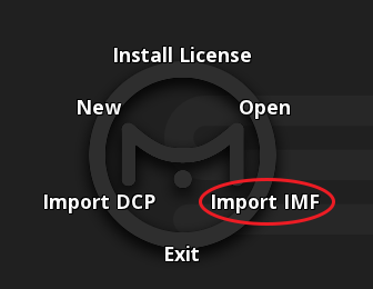
|
If the IMF has differential or supplement packages then their additional essences (if any) are imported to the same chosen media folder as the original IMF’s essences. Each CPL of the package will be a Composition of the Project. This way the operator may import a multiple CPLs IMF in a single process and easily switch between the different Compositions. |
Select the Package Directory
-
Select the IMF to import using the browse button:
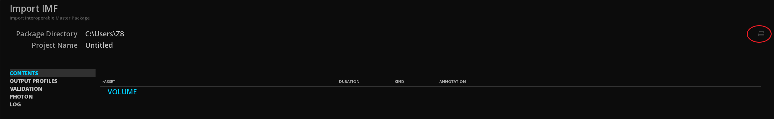
Once you have selected the package folder, and pressed OK, the contents get quickly analyzed and the various elements are then displayed in the exploded directory tree-view. You may scroll through the directory tree and expand or collapse individual elements by clicking on the plus and minus signs to the left of each item:
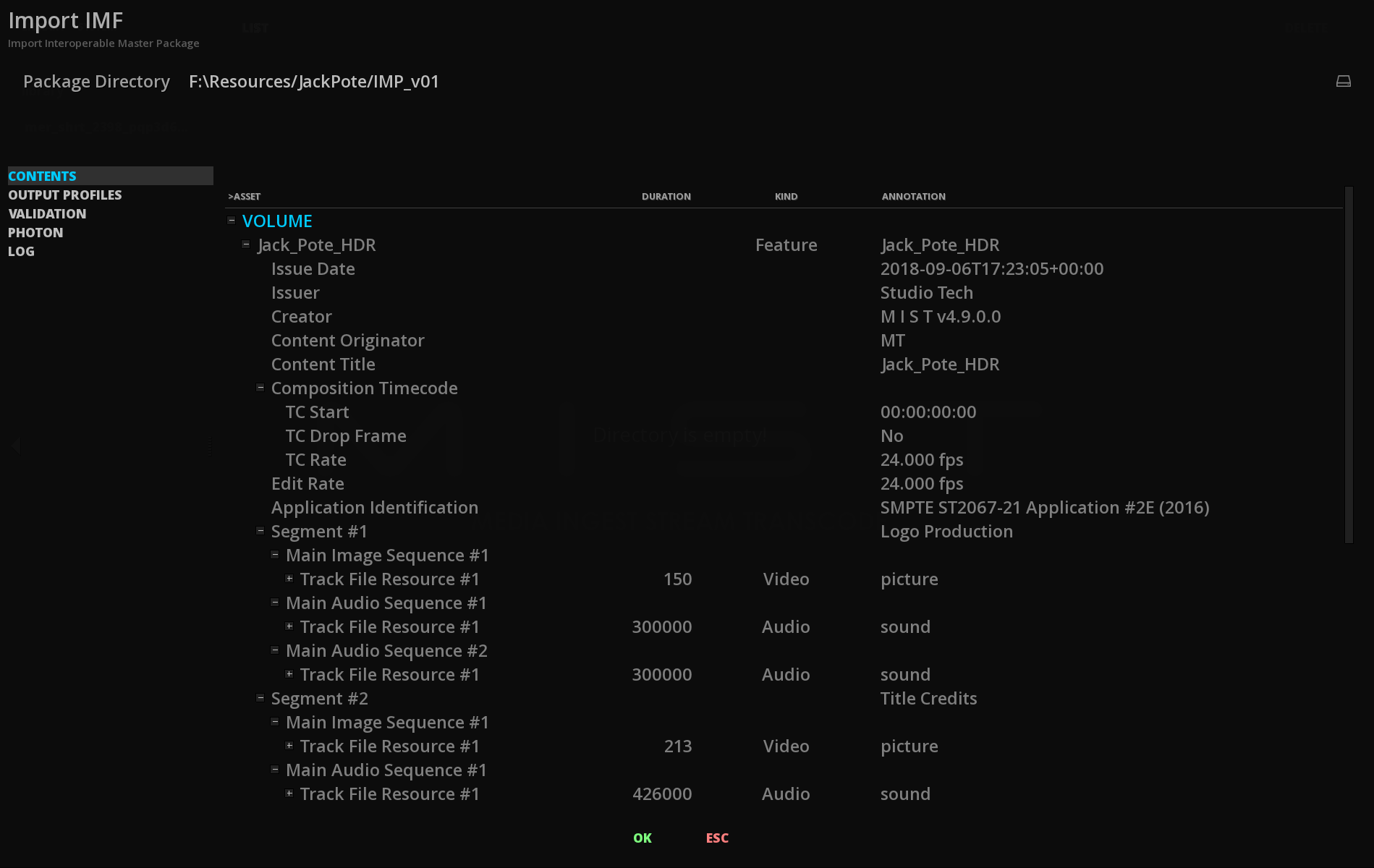
|
Do not modify the folder’s name or contents in any way or you risk destroying the IMF. |
In the screen shot above, the various composition playlists are displayed. Each of them contains one or more reels. These reels also contain a video track and optionally audio tracks and subtitles.
The name of each asset is displayed in the left most column while additional metadata is displayed in the remaining columns as available or relative to the asset itself. This may help to quickly identify the contents of a particular IMF and its sub versions before going through the actual process of importing it, especially if the IMF name does not provide the information you need to do so. This may be the case with sub versions or with multi-segments IMFs.
Project Name
This is where you chose a name for your Project that will contain the entire contents of the DCP you wish to import. By default the folder’s name of the DCP will be displayed.
-
To modify the name of the Project, click on the Name text field, enter a new name and press Enter or click outside of the Name text field.
14.2. IMF Validation
Using the IMF Import Tool from the starting menu, it is possible to validate the content of your package.
14.2.1. Contents
The Contents window displays what is present in the IMF: resources, sidecars, metadata are clearly displayed for an immediate overview of the package.
|
it can be very useful in the case of an HDR IMF to check the presence of metadata at this step: |
You can develop details for each resource by clicking on the “+” button or close it with the “-“ button:
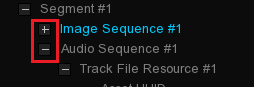
Use the mouse wheel to go down to the asset list.
14.2.2. Output Profiles
The Output Profiles tab display the list of the OPLs present in the package.
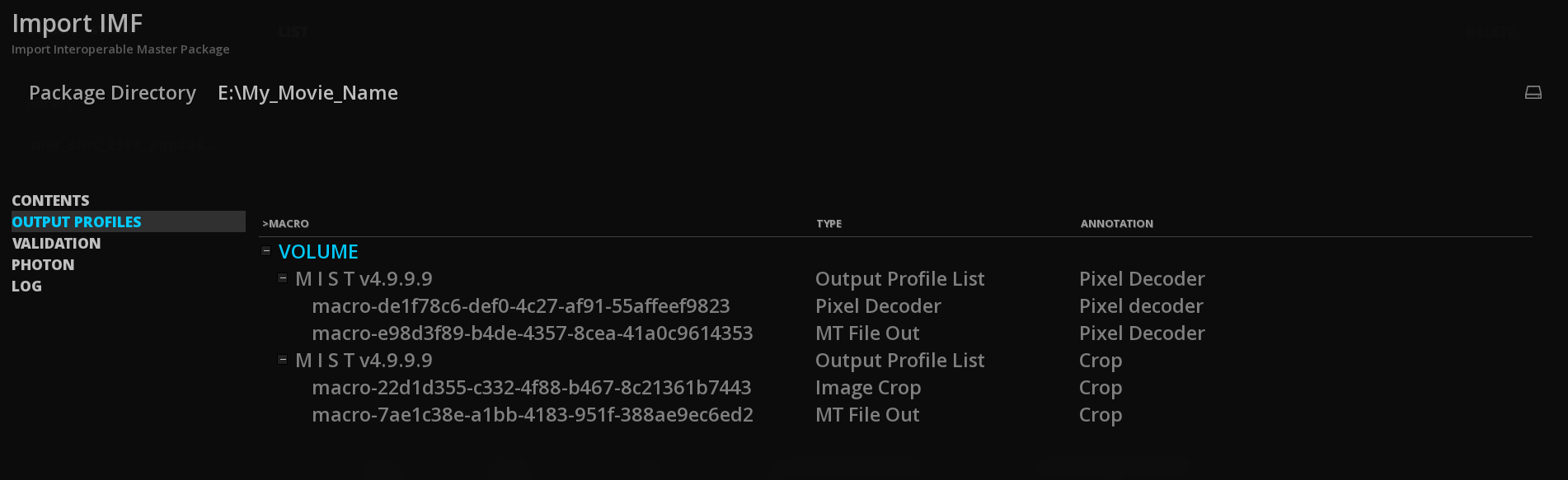
14.2.3. Validation
The Validation tool allows to verify the integrity and compliance of the IMF package as well as the type of application used. This is done by launching for each category some analysis tests. Each test name is briefly described in the TEST column.
-
You can do a full scan by clicking SELECT ALL. A small yellow line appears next to the tests to be performed. Click on EXECUTE to start the analysis tests:
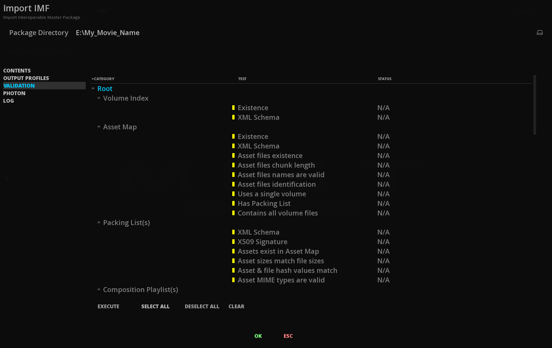
Once the validation test is complete, the status is displays using three labels:
| PASSED |
the test was passed successfully. |
| WARNING |
the test is irrelevant. This does not cause the package to fail. It may mean that the package is not concerned by the test. For example, if an IMF does not use a digital signature, the X509 test will appear as a WARNING label in order to attract attention on it. |
| FAILED |
the test has failed. |
| NOT RELEVANT |
the test is not relevant for the type of package being scanned. |
|
The tests validating the Applications verify all supported applications. Therefore it is normal that the ones not concerned by the IMF package appears as fail. Note that it is possible that several applications are present in the package. |
-
You can save the results of the validation as a PDF file by clicking on the button SAVE. This file will detail all the test results with explanations of the tests done allowing you to know what test have failed.
An explanation of the validation tests can be found in the Appendix IMF Validation.
14.2.4. Photon
Photon is an open source tool for parsing, interpreting and validating constituent files that make an Interoperable Master Package. This validation test is a supplemental tool to check the IMP and is integrated into Netflix ingestion Pipeline among others companies. Because this validation test is critical for some deliveries, especially for Application 2e, we frequently update the version of Photon.
-
To start an analysis, click on EXECUTE at the bottom left corner of the window.
|
For now, Photon is not yet capable of validating an IMF Dolby Vision package. |
APPENDICES
1. About ICE configuration
An ABOUT section in ICE gives you the essential overview about your system configuration.
It displays information the installed version of the system and its release date. When asking for some support, this information panel will help the user answering the first question: “on what version of ICE are you working on?”
-
The ABOUT section is accessible by pressing the keyboard key F12.
1.2. License Information
This panel recaps what options are included with the current License (if any).
1.3. System Information
This panel displays information about the system that runs ICE, like number of processors used or the type of GPU.
2. Where to find certificates for ICE
2.1. Public Certificate containing its Public Key and Digital Signature
Name |
ICE.cert.sha256.crt |
Location |
C:\Users\your_login_name_here\AppData\Roaming\Marquise Technologies\certificates |
Purpose |
This file contains ICE’s public key and digital signature. It must to be sent to any DCI mastering station that needs to create a secure DCP for use by ICE. |
2.2. Public Certificate Chain
Name |
ICE.chain.sha256.pem |
Location |
C:\Users\your_login_name_here\AppData\Roaming\Marquise Technologies\certificates |
Purpose |
This file contains the entire certificate chain of digital signatures of the ICE. It is required if the certificate needs to be verified. It may be distributed freely in accompaniment with the Public Leaf Certificate. .pem = Privacy-enhanced Electronic Mail. |
3. Input File Formats Support
3.1. Compositions
| Format Name | File Extension(s) |
|---|---|
Advanced Authoring Format |
.aaf |
D-Cinema Composition Playlist |
.xml |
EDL CMX 3600 |
.edl |
Final Cut Pro |
.xml |
Final Cut Pro X |
.fcpxml |
IMF Composition Playlist |
.edl |
3.2. Camera Files
| Camera | Models | Format Names |
|---|---|---|
Apple |
iPhone |
h.264 QT MOV |
ARRI |
Alexa (B6W, LF, SXR, SXT, XR, XT, 65) |
ARRIRAW (incl. 4:3), ARRIRAW MXF |
BlackMagic |
Cinema, Pocket Cinema, URSA |
Cinema DNG |
Canon |
EOS 1D / 5D / 7D |
h.264 QT MOV |
GoPro |
Any |
h.264 MP4 |
Nikon |
DSLR cameras |
NEF DSLR RAW |
Panasonic |
Varicam 35 |
Panasonic VRW RAW |
Phantom |
4K Flex |
.cine RAW |
RED |
Dragon |
REDCODE RAW (R3D) |
SONY |
F65, F55, F5 |
SonyRAW |
3.3. Image Sequences
| Format Name | File Extension(s) | Comment |
|---|---|---|
Cineon |
.cin |
|
DPX |
.dpx |
|
Targa |
.tga |
|
TIFF |
.tif, .tiff |
|
ARRI |
.ari |
|
SGI |
.sgi, .rgb |
|
JPEG |
.jpg, .jpeg |
|
JPEG2000 (J2K) |
.j2k, .j2c |
|
JPEG XS |
.jxs |
|
JPEG High Throughput |
.jph |
|
BMP |
.bmp |
|
PNG |
.png |
|
Photoshop PSD |
.psd |
Import composite image only. |
OpenEXR |
.exr |
|
ERIMovie |
.eri |
|
Chyron |
.chr |
|
Media Logic Artisan |
.art |
|
Rendition |
.6rn |
|
DNG |
.dng |
|
Weisscam RAW |
.fhgW* |
|
Canon RAW |
.rmf |
|
Panasonic VRAW |
.vrw |
3.4. Video
| Format Name | File Extension(s) |
|---|---|
Advanced Systems Format (Windows Media Video) |
.wmv |
AS-02 |
.mxf |
AS-10 |
.mxf |
AS-11 DPP |
.mxf |
AS-11 D10 |
.mxf |
ARD/ZDF/HDF |
.mxf |
AVI |
.avi |
Avid MXF |
.mxf |
DV |
.dv |
FlashVideo |
.flv |
GXF |
.mxf |
D10 |
.mxf |
RDD9 |
.mxf |
Matroska |
.mkv |
MPEG-2 |
.mpg, .mpeg |
MPEG-4 |
.mp4 |
MPEG-TS |
.mts |
MPEG-TS BDAV |
.m2ts |
MXF OP-Atom |
.mxf |
MXF OP-1a |
.mxf |
Motion JPEG2000 |
.mj2 |
PhantomCINE |
.cine |
QuickTime |
.mov |
R3D |
.r3d |
WebM |
.webm |
3.5. Audio
| Format Name | File Extension(s) |
|---|---|
Audio Interchange File Format (AIFF) |
.aif, .aiff |
Waveform Audio File Format (WAVE) |
.wav |
Free Lossless Audio Codec (FLAC) |
.flac |
3.7. Subtitles & Captions
| Format Name | File Extension(s) | Comments |
|---|---|---|
Cheetah Closed Captions |
.cap |
|
CineCanvas |
.xml |
|
Digital Cinema XML |
.xml |
|
EBU STL |
.stl |
|
EEG 708 Captions |
.xml |
|
Scenarist Closed Captions |
.scc |
|
Screen Electronics PAC |
.pac |
|
Sony BDN |
.xml, .png, .tif |
|
Spruce STL |
.stl |
|
SubRip |
.srt |
|
SubViewer |
.sub |
|
TTML |
.xml, .ttml |
|
Apple iTunes Timed Text |
.itt |
|
Common File Format Timed Text |
.xml |
|
DFXP |
.xml, .dfxp |
|
EBU-TT-D |
.xml |
|
Internet Media Subtitles and Captions (IMSC) |
.xml, .ttml |
Support for v1. and v1.01. Animation not supported. |
SMPTETT |
.xml |
|
WebVTT |
.vtt |
3.8. IMF Applications
The following IMF packages can be imported:
-
Application 2, 2e (Studio Profile)
-
Application 4 (Cinema Mezzanine)
-
Application 5 (ACES)
-
IMF ProRes RDD45
-
SMPTE TSP-2121-1 Application DPP (ProRes)
-
SMPTE TSP-2121-4 Application DPP (JPEG2000)
Supported JPEG2000 profiles:
-
Broadcast profiles, up to BPC L7
-
IMF profiles, up to 16 bit
4. Keyboard Shortcuts
Below is a recapitulation of the available Keyboards Shortcuts for ICE.
| TOPIC | MODIFIER KEY | DESCRIPTION |
|---|---|---|
NAVIGATION |
F1 |
Go to Project |
NAVIGATION |
F6 |
Go to Composition Analysis |
NAVIGATION |
Alt+F6 |
Go to Video Pipeline Diagram |
NAVIGATION |
F7 |
Go to Storyboard |
NAVIGATION |
F10 |
Go to Timeline |
NAVIGATION |
F11 |
Switch Calibrate/Timeline |
NAVIGATION |
F12 |
About |
NAVIGATION |
Esc |
Escape from current operation |
NAVIGATION |
H |
Help |
NAVIGATION |
Page Up |
Show Timeline |
NAVIGATION |
Page Down |
Hide Timeline |
NAVIGATION |
Ctrl+Q |
Exit Project |
NAVIGATION |
Alt+Ctrl+Esc |
Minimize |
NAVIGATION |
Alt+F2 |
Toggle Library access |
CLIP MANAGEMENT |
Ctrl+Shift+P |
Show Clip Properties |
OTHER |
Ctrl+F12 |
Take Snapshot |
AUDIO |
Alt+Shift+A |
Show/Hide Audio Mixer |
DISPLAY |
Shift+H |
Show/Hide Histogram |
DISPLAY |
Shift+V |
Show/Hide Vectorscope |
DISPLAY |
Shift+W |
Show/Hide Waveform |
DISPLAY |
Shift+A |
Show/Hide Audio levels |
DISPLAY |
Shift+B |
Show/Hide Bitrate |
DISPLAY |
Shift+N |
Show/Hide Luminance Meter |
DISPLAY |
Shift+D |
Show/Hide DMCVT Metadata |
DISPLAY |
Shift+M |
Show/Hide Dynamic Metadata |
DISPLAY |
Shift+P |
Show/Hide PSNR Meter |
DISPLAY |
Alt+Z |
Show/Hide Zebra |
DISPLAY |
Alt+Q |
Show/Hide Dynamic Mapping |
DISPLAY |
Alt+T |
Change time display |
DISPLAY |
F |
Fit Viewport |
DISPLAY |
Shift+F |
Toggle Full Screen Viewport |
DISPLAY |
C |
Center Viewport |
DISPLAY |
Alt+C |
Toggle Camera View |
DISPLAY |
Alt+F |
Toggle Safe Frames |
DISPLAY |
Alt+A |
Toggle Axis View |
DISPLAY |
Alt+K |
Show/Hide Color Picker Info |
DISPLAY |
Alt+Shift+K |
Toggle Color Picker Display Modes |
DISPLAY |
Alt+J |
Show/Hide Information |
DISPLAY |
Alt+1 |
Toggle Red Channel |
DISPLAY |
Alt+2 |
Toggle Green Channel |
DISPLAY |
Alt+3 |
Toggle Blue Channel |
DISPLAY |
Alt+4 |
Toggle Alpha Channel |
DISPLAY |
Alt+5 |
Toggle Mask |
DISPLAY |
Alt+B |
Toggle Active Area |
DISPLAY |
Alt+S |
Toggle Mono/Stereo |
DISPLAY |
Alt+D |
Toggle Left/Right Display |
DISPLAY |
Alt+G |
Toggle Geometry Display |
DISPLAY |
X |
Toggle Dual Viewport |
DISPLAY |
Alt+X |
Toggle Single/Dual Viewport |
DISPLAY |
G |
Lock Dual Viewport |
LUT |
9 |
Toggle LUT Computer Display |
LUT |
0 |
Toggle LUT Mastering Display |
TIMELINE |
Ctrl+Shift+F |
Fit Timeline |
TIMELINE |
Alt+Ctrl+F |
Fit duration |
TIMELINE |
Alt+Ctrl+Shift+F |
Fit All durations |
TIMELINE |
Ctrl+Shift+C |
Center Timeline |
TIMELINE |
Ctrl++ |
Zoom In Timeline |
TIMELINE |
Ctrl+- |
Zoom Out Timeline |
TIMELINE |
Alt+H |
Toggle Clip Handles |
EDIT |
Ctrl+Z |
Undo |
EDIT |
Ctrl+Y |
Redo |
EDIT |
Ctrl+A |
Select all Clips |
EDIT |
Ctrl+D |
Deselect All Clips |
EDIT |
Del |
Delete Selected Clips |
EDIT |
Backspace |
Ripple Delete Selected Clips |
EDIT |
I |
Mark In |
EDIT |
O |
Mark Out |
EDIT |
Alt+I |
Clear Mark In |
EDIT |
Alt+O |
Clear Mark Out |
EDIT |
Ctrl+Shift+I |
Set Composition In |
EDIT |
Ctrl+Shift+O |
Set Composition Out |
EDIT |
Alt+M |
Clear Mark points |
EDIT |
Ctrl+K |
Razor at time marker |
EDIT |
Ctrl+L |
Lift marked region |
EDIT |
Ctrl+E |
Extract marked region |
EDIT |
Ctrl+J |
Join |
EDIT |
Insert |
Toggle Insert/Replace Mode |
EDIT |
Ctrl+C |
Copy |
EDIT |
Ctrl+V |
Paste |
EDIT |
S |
Select Current Clip |
EDIT |
Ctrl+Up |
Activate Layer Above |
EDIT |
Ctrl+Down |
Activate Layer Below |
EDIT |
Ctrl+Shift+L |
Lock/Unlock Active Layer |
EDIT |
Ctrl+Shift+E |
Enable/Disable Active layer |
EDIT |
T |
Insert Dissolve |
EDIT |
Y |
Insert from Source |
EDIT |
Ctrl+Shift+A |
Insert Audio layer |
EDIT |
Ctrl+Shift+V |
Insert Video Layer |
EDIT |
Ctrl+Shift+W |
Merge Stereo Video Layers |
EDIT |
Alt+Ctrl+V |
Paste Layered |
EDIT |
W |
Toggle Snap |
EDIT |
Alt+Left |
Trim In -1 frame |
EDIT |
Alt+Right |
Trim In +1 frame |
EDIT |
Alt+Shift+Left |
Trim Out -1 frame |
EDIT |
Alt+Shift+Right |
Trim Out +1 frame |
EDIT |
Alt+Ctrl+Left |
Slip -1 frame |
EDIT |
Alt+Ctrl+Right |
Slip +1 frame |
EDIT |
Alt+Up |
Slide -1 frame |
EDIT |
Alt+Down |
Slide +1 frame |
TRANSPORT |
J |
J Pressed |
TRANSPORT |
J |
J Released |
TRANSPORT |
K |
K Pressed |
TRANSPORT |
K |
K Released |
TRANSPORT |
L |
L Pressed |
TRANSPORT |
L |
L Released |
TRANSPORT |
Space |
Play Forwards |
TRANSPORT |
Ctrl+Space |
Play Backwards |
TRANSPORT |
Alt+Space |
Play Forwards Marked Range |
TRANSPORT |
Alt+Ctrl+Space |
Play Backwards Marked Range |
TRANSPORT |
Shift+I |
Go to IN point |
TRANSPORT |
Shift+O |
Go to OUT Point |
TRANSPORT |
Left |
Previous Frame |
TRANSPORT |
Right |
Next Frame |
TRANSPORT |
Shift+Left |
Previous 10 Frames |
TRANSPORT |
Shift+Right |
Next 10 frames |
TRANSPORT |
Ctrl+Left |
Previous 100 Frames |
TRANSPORT |
Ctrl+Right |
Next 100 Frames |
TRANSPORT |
Ctrl+Shift+Left |
Go to Previous Cut |
TRANSPORT |
Ctrl+Shift+Right |
Go to Next Cut |
TRANSPORT |
Home |
Go to First Frame of the Composition |
TRANSPORT |
End |
Go to Last Frame of the Composition |
TRANSPORT |
Ctrl+P |
Toggle Playback Mode |
TRANSPORT |
Shift+Home |
Go to Layer Start |
TRANSPORT |
Shift+Eend |
Go to Layer End |
TRANSPORT |
Ctrl+Home |
Go to Clip Start |
TRANSPORT |
Ctrl+End |
Go to Clip End |
TRANSPORT |
Alt+Page Up |
Previous Audio Cut |
TRANSPORT |
Alt+Page Down |
Next Audio Cut |
TRANSPORT |
Shift+Page Up |
Previous Subtitle |
TRANSPORT |
Shift+Page Down |
Next Subtitle |
MARKERS |
Alt+U |
Previous Composition Marker |
MARKERS |
Shift+U |
Next Composition Marker |
MARKERS |
Alt+CTRL+M |
Previous Segment Marker |
MARKERS |
Ctrl+Shift+M |
Next Segment Marker |
MARKERS |
Ctrl+M |
Add Composition Marker |
MARKERS |
Alt+Shift+M |
Add Segment Marker |
STILL STORE |
8 |
Enter/Toggle Compare Mode |
STILL STORE |
Alt+8 |
Exit Compare Mode |
STILL STORE |
Ctrl+8 |
Copy Frame to Still Store |
STILL STORE |
Ctrl+Shift+8 |
Toggle Comparator Visibility |
EVENT VIEWER |
E |
Show/Hide Event Viewer |
REELS |
Alt+Ctrl+Page Up |
Previous reel |
REELS |
Alt+Ctrl+Page Down |
Next reel |
5. Validation
In this section you will find some detailed explanations of the different validation tests performed for DCP and IMF Packages.
5.1. DCP Validation
5.1.1. Conformity
This test checks that the all assets including the ASSETMAP follow the VOLINDEX compliance (i.e. strictly either SMPTE or InterOp).
| A failure on this tests may prevent ingest or playback. --- |
5.1.2. Composition Playlist
- Is TKR (Theatre Key Retrieval) Enabled
-
This test checks that Theatre Key Retrieval (TKR) is enabled for the Composition Playlist(s).
| A failure on this test DOES NOT prevent ingest or playback. |
- Reel & Track Intrinsic Durations Match
-
This test checks that the reel intrinsic durations and track file intrinsic durations match.
| A failure on this test could prevent ingest or playback. |
- Reel Durations Are Valid
-
This test checks that the reel durations match the asset durations. A failure on this test could prevent ingest or playback.
- Reel Tracks Are Homogeneous
-
This test checks that all the reels of a Composition Playlist have the same track configuration (i.e. picture/audio/subtitles).
| A failure on this test could prevent ingest or playback on some systems. |
- Reels Have Audio
-
This test checks that the reels have an audio track.
| A failure on this test could prevent ingest or playback. |
- Reels Have Picture
-
This test checks that the reels have a picture track.
| A failure on this test could prevent ingest or playback. |
- Track Encryption is Homogeneous
-
This test checks that the tracks across the reels have a homogeneous encryption status.
| A failure on this test should not prevent ingest or playback. |
5.1.3. Key Delivery Message
- Lifetime Is Valid
-
This test checks if the lifetime of the Key Delivery Message(s) matches the lifetime of the signing certificates.
| A failure on this test will prevent the ingest of the KDM(s). |
- Metadata Is Valid
-
This test checks if the metadata in the Key Delivery Message(s) is valid.
| A failure on this test will prevent the ingest of the KDM(s). |
- X509 Signature
-
This test checks for the presence of the X509 digital signature in the Key Delivery Message(s).
| Digital signature is mandatory, if not present the KDM(s) is/are not valid and ingest will fail. |
5.1.4. Trackfile(s)
- Frame Boundaries Are Valid
-
This test checks that the first and last frame of the track file can be accessed. A failure on this test could prevent ingest or playback. This test checks that the first and last samples of the track file can be accessed.
| A failure on this test could prevent ingest or playback. |
- Trackfile(s) last at least one second
-
This test checks that the trackfiles last at least one second.
| A failure on this test could prevent correct playback on some old servers. |
- Picture Characteristics Are Valid
-
This test checks that the characteristics of the picture trackfiles are valid.
| A failure on this test could prevent ingest or playback. |
- Picture Data Rate Is Valid
-
This test checks that the bitrate of the picture trackfiles is valid.
| A failure on this test could prevent correct playback. |
- Sound Characteristics Are Valid
-
This test checks that the characteristics of the sound trackfiles are valid.
A failure on this test could prevent ingest or playback.
- Subtitle Font File Resources Are Valid
-
This test checks that the font file resources are valid (i.e. must be OTF or TTF format).
| A failure on this test could prevent ingest or playback. |
- Subtitle Font File Sizes Are Valid
-
This test checks that the font file sizes are valid (i.e. do not exceed 640kB for InterOp).
| A failure on this test could prevent ingest or playback. |
5.2. IMF Validation
5.2.1. Composition Playlist
- Has Extension Properties
-
This test checks the presence of the application ExtensionProperties in the Composition Playlist(s).
- Has Timecode
-
This test checks the presence of the timecode information inside the Composition Playlist(s).
- Edit Rate Is Homogeneous
-
This test checks if the EditRate of the resource(s) matches the Edit Rate of the Composition Playlist(s).
- Has At Least One Content Version ID
-
This test checks if at least one ContentVersion instance is present in the Composition Playlist(s).
- Has At Least One Main Audio Virtual Track
-
This test checks if at least one MainAudio virtual track is present in the Composition Playlist(s).
- Has Exactly One Main Image Virtual Track
-
This test checks if one and only one Main Image virtual track is present in the Composition Playlist(s).
- Has Homogenenous Virtual Track Durations
-
This test checks that all the virtual tracks in the Composition Playlist(s) has the exact same duration.
- Segment Durations Are Valid
-
This test checks that the duration of segments is valid. The duration constraints depended on the edit rate. For non-integer edit rates the duration of a segment must be a multiple of 5 frames.
5.2.2. Output Profile List
- Composition Playlist Exists In Volume
-
This test checks that the Composition Playlist referenced by the Output Profile List exists in the volume. A warning indicates that the Composition Playlist is external to this volume.
- Has Exactly Once Preset Macro
-
This test checks that Simple OPLs contain a single Preset Macro instance.
| OPLs with more than one Preset Macro are invalid and result in an ingest failure. |
- Macro Names Are Unique
-
This test checks that each macro in the Output Profile List(s) has a unique name.
| Duplicate names will result in an ingest failure. |
- Preset Macro Is Defined
-
This test checks that Preset Macro(s) use a predefined URI known to the local host.
| Unknown URIs will not trigger any preset macro processing. |
- X509 Signature
-
This test checks for the presence of the X509 digital signature in the Output Profile Lists(s).
| Digital signature is optional, unless the assets are encrypted. |
- XML Schema
-
This test checks the XML schema of the Output Profile List file(s).
| An error in the XML schema validation may result in an ingest failure. |
5.2.3. Trackfile(s)
- Essence Boundaries Are Valid
-
This test checks that the first and last frame/sample of the of a track file can be accessed.
| A failure on this test could prevent ingest or playback. |
- Image Characteristics
-
This test checks the image characteristics of the track files against the the Application Specification constraints.
| A failure on this test may prevent ingest and/or playback on some systems. |
5.2.4. Asset Map
- Contains All Volume Files
-
This test checks if all the files contained in the volume are referenced in the ASSETMAP file.
| A volume that contains non referenced files might fail to ingest. |
- Exists
-
This test checks the presence of the ASSETMAP file at the root directory of the volume.
| A package cannot be opened without this file. |
- File Names
-
This test checks that all the files listed in the ASSETMAP have a name that is compliant with the restrictions listed in ST429-9:2014 Annex A. These restrictions imply that path segments and file name do not contain other characters than: {a..z, A..Z, ., _, -}.
| File names that does not follow the rules listed in ST429-9:2014 Annex A may fail to ingest and/or prevent playback. |
- File Sizes
-
This test checks that all the files listed in the ASSETMAP have a size that exactly matches the stored size.
| A file with a size different from the one found in the ASSETMAP is probably corrupted and may fail to ingest. |
FOR MORE INFORMATION PLEASE CONNECT TO OUR SUPPORT PORTAL: https://marquise-tech.cloud/